measurement,shortthetestleadsanduseRELfunction.
• Iftheresistancewhenshortedismorethan0.5Ω,pleasecheckiftestleadsare
loosenedordamaged.
• Whenmeasuringhighresistanceabove60MΩ,itisnormaltotak eafewseconds
tosteadythereadings.
• Resistancemeasurementcanbeusedtoinspectdevice’sinternalfuses.(see
figure4b)
• DonotinputvoltageoverDC60VorAC30V.
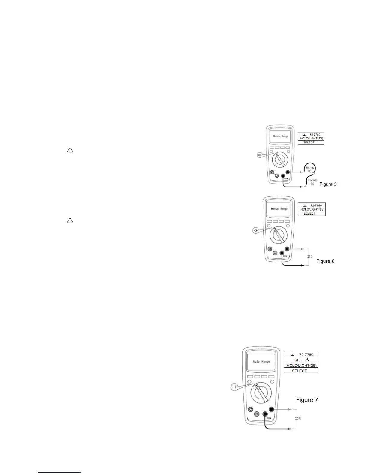
3. Continuitymeasurement(seefigure5)
Iftheresistancebeingmeasuredisover150Ω,circuitisinopen
status,buzzerdoesnotgooff.Iftheresistancelessthan10Ω,
circuitisingoodconductionstatus,buzzerwillcontinuouslygooff.
Note:
• Toavoidda magetothedevice,beforemeasuringcontinuity,
switchoffallpowersuppliesandfullydischargeallcapacitors.
• DonotinputvoltageoverDC60VorAC30V.
4. Diodemeasurement(seefigure6)
“OL”symbolappearswhenthediodeisopenorpolarityis
reversed.
ForsiliconPNjunction,normalvalue:500~800mV(0.5~0.8V).
Notes:
• Switchoffthepowersupplytothecircuit,andfullydischarge
allcapacitors
• Voltagefortestingdiodeisabout3.1V.
• DonotinputvoltageoverDC60VorAC30V.
5. Capacitancemeasurement(seefigure7)
Whenthereisnoinput,thedevicedisplaysafixedvalue
(intrinsiccapacitance).Forsmallcapacitance
measurement,toensuremeasurementaccuracy,the
measuredvaluemustbesubtractedfromintrinsic
capacitance.Oruserscanmeasuresmallcapacity
capacitorswithrelativemeasurementfunction(REL)(the
devicewillautomaticallysubtracttheintrinsic
 Loading...