46
test lead into the COM terminal.
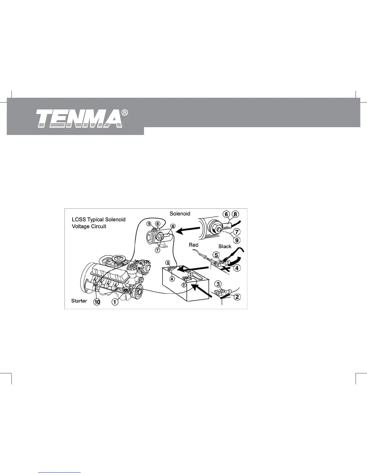
3. Refer to the LOSS typical trigger voltage circuit. (See figure 15)
Test the voltage between any of the following pairs of points respectively:
1&2, 2&3, 4&5, 5&6, 6&7, 7&8, 8&9, 8&10
(Figure 15)
Component Voltage
Switch 300 mV
72-9280: OPERATING MANUAL
 Loading...