3-5
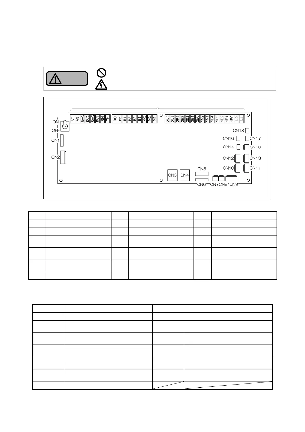
3.2.4 Control board
The following are the details of the control board.
Warning
Do not remove the protective cover on the control board or the cover of
the I/O terminal block when the power is turned on.
Otherwise, it may lead to an electric shock.
Table 3-2-4 (a) Connector assignments
No. Connected to No. Connected to No. Connected to
CN1 Device in panel CN7 Device in panel CN13 Flow switch No.2
CN2 (Not in use) CN8 Device in panel CN14 (Not in use)
CN3 Device in panel CN9 (Not in use) CN15
Control panel
high-temperature sensor *
1
CN4 Device in panel CN10 Pressure transmitter CN16
High-temperature sensor
No.1
CN5 (Not in use) CN11 (Not in use) CN17
High-temperature sensor
No.2
CN6 Device in panel CN12 Flow switch No.1 CN18 Low-temperature sensor *
2
*1 For models fitted with outdoor cover, this sensor is connected depending on the specifications.
*2 The low-temperature sensor is connected only to freeze-proof models (special specifications).
Table 3-2-4 (b) Designations and applications of I/O terminal block
Designation Application Designation Application
IL1, IL2 Interlocking signal B1 to B5 Alarm signal output
1E0 to 1E4
Receiver tank No.1 level detection
electrode
BC Alarm signal output common
2E0 to 2E4
Receiver tank No.2 level detection
electrode
VR, VT Alarm power (power voltage)
1N1, 1N2
Receiver tank No.1 solenoid valve
control electrode
RH, TH*
3
Freeze-proof heater (power voltage)
2N1, 2N2
Receiver tank No.2 solenoid valve
control electrode
SVC, SV1
Receiver tank No.1 solenoid valve
(power voltage)
M1, M2 No.1, No.2 operation signal SVC, SV2
Receiver tank No.2 solenoid valve
(power voltage)
MC Operation signal common
*3 The freeze-proof heaters are connected only to freeze-proof models (special specifications).
I/O terminal block
Operation
power
switch
Control board
Fig. 3-2-4 Detailed drawing of control board