3-6
3.3 Specifications of control panel
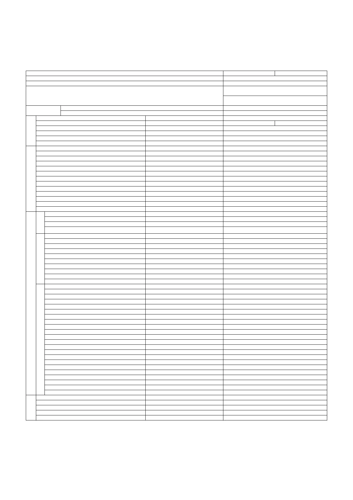
Table 3-3 Specifications of control panel
Item Specifications 1 Specifications 2
Control panel model BQNXC
Operation mode Automatic alternate/automatic alternate parallel
0.4 to 3.7 kW: ACS resin (light gray/material color) +
steel plate (highly corrosion-resistant hot-dip plating)
Material and external color of casing
5.5, 7.5 kW: steel plate (Munsell 5Y7/1
semigloss/baking finish)
Single-phase 200/200-220 V (50/60 Hz) 0.4 to 1.1 kW
Output Range
Three-phase 200/200-220 V (50/60 Hz) 0.4 to 7.5 kW
Ground fault interrupter Individual pump systems S
Power-factor correcting reactor (DCR) Individual pump systems 㸫 S
Motor protection 㸫 Inverter (electronic thermal protection)
Double receiver tank circuit Can be switched on the operation panel S
Inflow solenoid valve circuit Can be operated on the operation panel S
Circuit
configuration
Electrode 5P circuit 㸫 S
Dry-run prevention 㸫 S
Automatic switching upon failure 㸫 S
Pump continuous operation prevention function 㸫 S
Pump operation time equalization function 㸫 S
Freeze-proof operation function 㸫 O
External stop signal (interlock) available a/b-contact available S
Buzzer stop timer setting 1 to 60 min, , no buzzer S
Full/low water alarm automatic recovery setting 㸫 S
Inflow solenoid valve automatic alternation setting 㸫 S
Inspection mode 㸫 S
Alarm buzzer 㸫 S
Buzzer stop switch 㸫 S
Functions
Energy-saving operation setting 㸫 S
Power 㸫 S
Operation (for each pump) 㸫 S
Block (for each pump) 㸫 S
Indicator
li
h
Alarm (collective) 㸫 S
Discharge pressure Unit: mH
2
O S
Power voltage Unit: V S
Operation current (for each pump) Unit: 0.1 A S
Operation frequency (for each pump) Unit: 0.1 Hz (only automatic) S
Cumulative operation time (for each pump) Unit: Hour S
Cumulative number of starts (for each pump) Unit: times S
Number of starts time of the unit Number of starts on the previous day S
Alarm log 5 latest alarms S
Interlocking in operation 㸫 S
Various indications
Freeze-proofing in progress 㸫 O
Receiver tank full No: E001 S
Receiver tank low No: E002 S
Dry-run prevention No: E003 S
Electrode failure No: E004 S
Start frequency failure No: E006 S
Pressure transmitter 1 failure No: E051 S
Control panel high temperature No: E070 O
EEPROM error No: E080 S
Overload (for each pump) No: E#01 S
Discharge pressure abnormal drop (for each pump) No: E#02 S
Electric leak (for each pump) No: E#03 S
High temperature (for each pump) No: E#04 S
Flow switch failure (for each pump) No: E#05 S
Overcurrent (for each pump) No: E#11 S
Overvoltage (for each pump) No: E#12 S
Anti-stall (for each pump) No: E#14 S
Inverter overload (for each pump) No: E#15 S
Open-phase output (for each pump) No: E#16 S
Inverter overheat (for each pump) No: E#17 S
Inverter communication failure (for each pump) No: E#18 S
Inverter trouble 1 (for each pump) No: E#19 S
Indications on control panel
Alarm indications
Inverter trouble 2 (for each pump) No: E#20 S
Power for alarm Power voltage S
Freeze-proof heater output Power voltage O
Inflow solenoid valve output Power voltage S (Normally open/closed type available)
Operation signal No-voltage a-contact S (for each)
External
output
Error signal No-voltage a-contact S (5 points: patterns 0 to 4)
“S” indicates standard features, and “O” indicates optional features.
*1 Power voltage and operation current values are estimated values. There is an error of approximately 10% with
respect to the full scale.
*2 “E006” and “E#04” can be disabled using settings. Refer to “7.5 Parameter setting.”
*3 The character “#” is replaced by the corresponding pump number.
*4 The open-phase output error is detected by only the units with the rated output of 5.5 kW or more.
*5 For the patterns to output error signals using external relays, refer to “7.5 Parameter setting.”