4-7
(2) External output signals
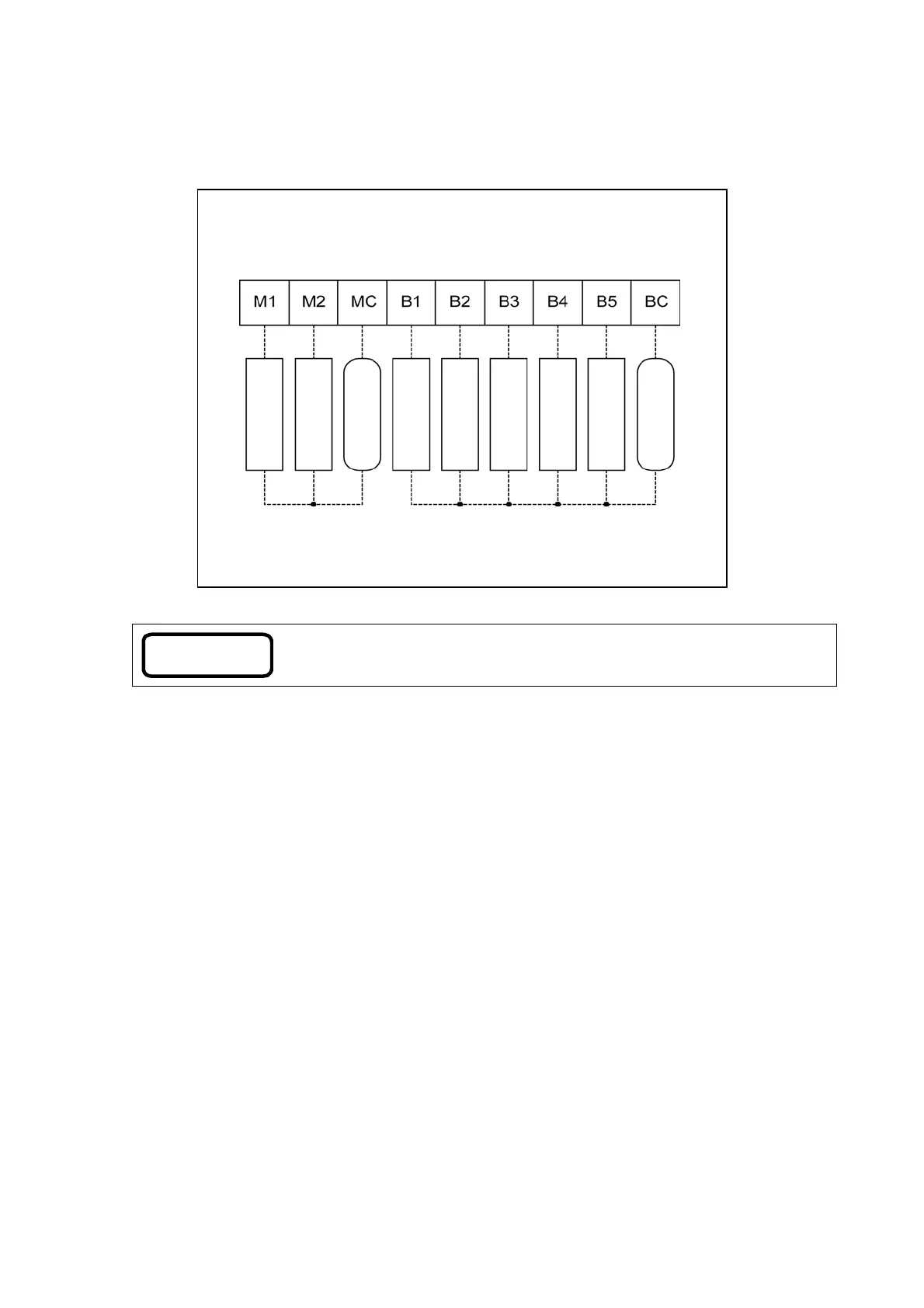
Connect wires to the external output terminals as shown in the following diagram.
Note
The parameter P100 allows you to select an external relay output pattern from
5 options.
For details and the setting method, refer to “7.5 Parameter setting.”
External output terminals
(I/O terminal block on control board)
Fig. 4-3-2(b) Settings for standard models
(Parameter P100: “0”)
#1 operation
#2 operation
Power
#1 failure
#2 failure
Receiver tank full
Dry-run prevention
Receiver tank low
Trouble
Power