EasyManua.ls Logo

TES TES-2700 User Manual

TES TES-2700
9 pages
To Next Page IconTo Next Page
Page #1 background imageLoading...
Page #1 background image
AUTO - RANGING
DIGITAL MULTIMETER
TES-2700
INSTRUCTION MANUAL
TES ELECTRICAL ELECTRONIC CORP.
1. SAFETY INFORMATION
Read the following safety information carefully before attempting to
operate or service the meter.
To avoid damages to the instrument do not apply the signals which
exceed the maximum limit s shown in the technical specifications tables.
Never measure current while the test leads are inserted into the input
jacks.
Do not use the meter or test leads if they look damaged. Use extreme
caution when working around bare conductors or bus bars.
Accidental contact with the conductor could result in electric shock.
Use the meter only as specified in this manual ; otherwise, the
protection provided by the meter may be impaired.
Read the operating instructions before use and follow all safety
information.
Caution when working with voltages above 60V DC or 30 V AC RMS.
Such voltages pose a shock hazard.
Before taking resistance measurements or testing acoustic continuity,
disconnect circuit from main power supply and all loads from circuit.
Safety symbols:
Caution refer to this manual before using the meter.
Dangerous voltages.
Meter is protected throughout by double insulation or
reinforced insulation.
When servicing, use only specified replacement
parts.
Comply with EN-61010-1
1
Question and Answer IconNeed help?

Do you have a question about the TES TES-2700 and is the answer not in the manual?

TES TES-2700 Specifications

General IconGeneral
BrandTES
ModelTES-2700
CategoryMultimeter
LanguageEnglish

Summary

SAFETY INFORMATION

General Safety Precautions

Read and follow safety information before operating or servicing the meter to avoid damage and ensure safe use.

High Voltage Hazard

Caution regarding shock hazard when working with voltages above 60V DC or 30 V AC RMS.

Safety Symbols Explained

Explains symbols for caution, dangerous voltages, insulation, and replacement parts for user safety.

FEATURES

SPECIFICATIONS

General Information & Environment

Details environment conditions, operation ambient, and maintenance/cleaning procedures for the multimeter.

Display Symbols & Range Selection

Defines display symbols and explains range selection, over-range, and low battery indications.

Electrical Specifications - Overview

Covers specifications for DC/AC Voltage, DC/AC Current, Resistance, Diode Test, and Continuity measurements.

Electrical Specifications - Details

Provides detailed electrical parameters including accuracy, impedance, and overload protection for various measurements.

Physical & Environmental Details

Details battery life, polarity, operating/storage conditions, dimensions, weight, and accessories.

PARTS & CONTROLS

Name of Parts and Positions

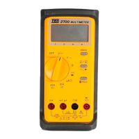
Identifies and locates various parts and controls on the multimeter using a diagram.

Connectors and Buttons

Explains the purpose of measuring connectors and the function of buttons like RANGE, HOLD, and AC/DC select.

LCD Display and Indicators

Describes the LCD display elements including measured values, units, and indicators like polarity, range, and battery status.

DC/AC Voltage Measurement Procedure

Step-by-step instructions for performing DC and AC voltage measurements with the multimeter.

DC/AC Current Measurement Procedure

Step-by-step instructions for performing DC and AC current measurements, including series connection.

Diode Test Procedure

Procedure for testing diodes, including connection, range selection, and interpretation of forward voltage.

Resistance Measurement Procedure

Guide to measuring resistance, including connection, range selection, and safety precautions before measurement.

Continuity Measurement Procedure

Instructions for performing continuity tests, including connection and beep indication for low impedance circuits.

BATTERY & FUSE REPLACEMENT

Battery Check-Up & Replacement

Instructions for checking battery status and replacing the two AAA 1.5V batteries when indicated.

Fuse Replacement

Procedure for replacing the fuse with a 0.5A/250A or 20A/600V fast blow type.

Related product manuals