15
a. The supplied voltage must be less than 12V and greater than 4.4V, otherwise the probe
could be damaged or can’t be operated properly.
b. Polarity is “+” inside and “–” outside. For wrong polarity, built-in circuit protects the
probe, no danger or damage will occur.
c. When the voltage of the cells become too low, the power indicator on the will flicker.
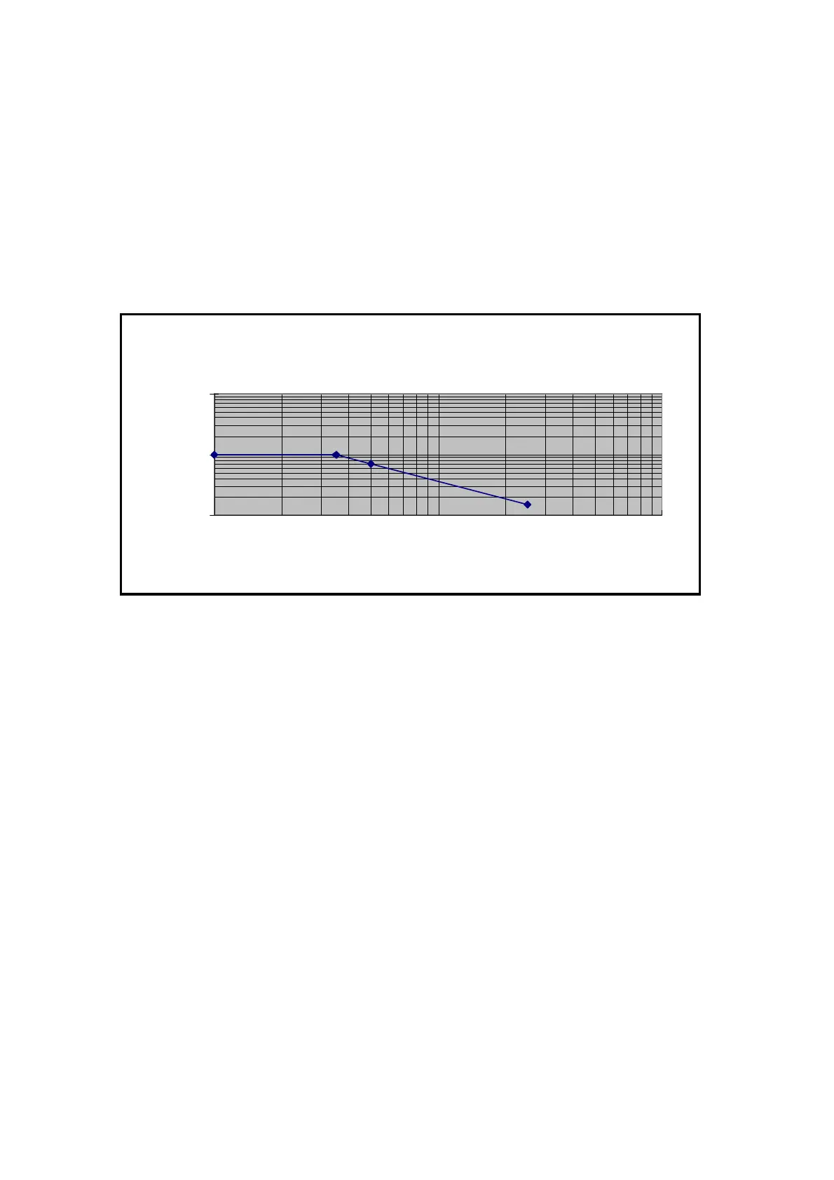
10. Derating Curve
The derating curve of the absolute maximum input voltage in common mode is shown as
follows and valid for both models TT-SI 9001 and TT-SI 9002.
11. Inspection Procedure
a. Connect the BNC output connector to the vertical input of a general purposed
oscilloscope.
b. Install four AA cells or connect an appropriate mains adaptor or power lead to the correct
line voltage.
c. Set the oscilloscope input coupling to DC and the 1V/div. Center the trace on the display.
d. Connect the inputs of the probe to power lines.
e. Set the range of the probe to 1/100 (TT-SI 9001) or 1/200 (TT-SI 9002).
f. Then, a 50Hz/60Hz sine-wave of proper amplitude will be displayed on the screen of the
oscilloscope and this means the probe is working properly.
12. Cleaning
Use a soft cloth to clean the dirt. Prevent damage to probe.
a. Avoid immersing the probe.
b. Avoid using abrasive cleaners.
c. Avoid using chemicals contains benzene or similar solvents.
1000
150
1000
700
100
1000
10000
1,0E+06 1,0E+07 1,0E+08
Frequency (Hz)
Voltage (Volt rms)