Chapter 3 – Operation
TestEquity FS Series Ovens Page 3-1
Chapter 3 – Operation
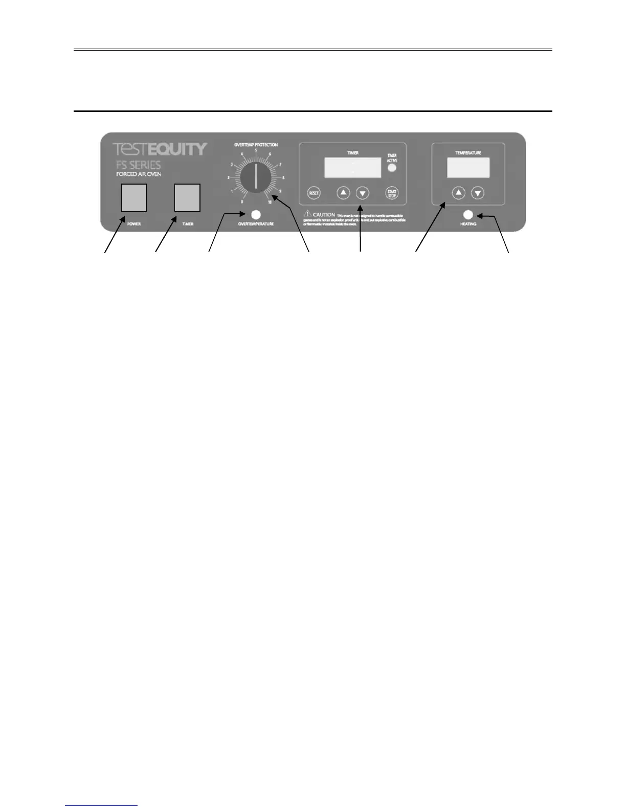
Front Panel Controls
Power Switch
(A) The POWER switch controls all power to the oven. It must be in the I (ON) position before
any systems are operational. The green light in the switch will be lit when the switch is ON.
Timer Switch
(B) The TIMER switch controls power to the timer circuit. In the O (OFF) position, the oven
heat is controlled with no timed duration. In the I (ON) position, heat is controlled for a timed
interval and then the heat shuts off at the end of that interval.
Overtemperature Protection Thermostat
(C) The OVERTEMP PROTECTION thermostat is an independent controller to protect against
any failure which would allow temperature to rise past the TEMPERATURE controller’s set
point. The adjustment knob points to a relative scale from 0 to 10.
Overtemperature Light
(D) The OVERTEMPERATURE pilot lamp is directly below the OVERTEMP PROTECTION
thermostat. The light will come on when the OVERTEMP PROTECTION is activated and has
taken control of the oven. This pilot lamp should never be on under normal operating conditions.
Timer
(E) The TIMER consists of a digital display, UP/DOWN arrow pads, a RESET pad, a
START/STOP pad and a TIMER ACTIVE light. The TIMER provides the ability to have the
oven maintain heat for a specified period of time.
Temperature Controller
(F) The TEMPERATURE controller consists of digital display and UP/DOWN arrow pads for
entering the temperature set point and for calibration.
Heating Light
(G) The HEATING pilot lamp will be lit whenever the heating elements are energized. It will
cycle on/off when the oven approaches and stabilizes at the desired temperature set point.
0
0