Do you have a question about the TESTO 176 and is the answer not in the manual?
Provides essential information about the document's purpose and guidelines.
Guidelines for safe operation and handling of the data logger.
Procedures for responsible disposal and environmental protection.
Describes the purpose and typical applications of the testo 176 data loggers.
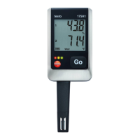
Provides detailed technical specifications for the testo 176 T1 model.
Instructions for unlocking and removing the data logger from its mounting bracket.
Steps for connecting the data logger to a computer for data transfer and configuration.
Information regarding the display of testo 176 models, including models without a display.
Explanation of the different LED indications and their meaning.
Overview of the main functions and button operations of the data logger.
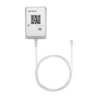
Guidelines for properly connecting sensors to the data logger and measuring points.
Guide to programming the data logger using the testo Comfort Software.
Explanation of the data logger's menu structure and display indicators.
Instructions for installing the wall bracket for the data logger.
Steps for attaching the data logger to the mounted wall bracket.
Procedures for retrieving recorded data via USB cable and SD card.
Step-by-step guide for replacing the internal battery of the data logger.
Guidelines for safely cleaning the data logger's housing and sensors.
Common questions and their solutions regarding data logger operation and error messages.
List of available accessories and spare parts for the testo 176 data loggers.
The Testo 176 series of data loggers are advanced instruments designed for saving and reading out individual readings and measurement series. These devices are ideal for a wide range of applications, from monitoring environmental conditions in warehouses to precise temperature measurements in industrial settings. Readings are measured and saved internally, and can then be transferred to a PC via a USB cable or SD card for evaluation using the Testo Comfort Software. This software also allows for individual programming of the data loggers, enabling users to customize settings to suit their specific needs.
The core function of the Testo 176 data loggers is to accurately measure and record various parameters over time. Depending on the specific model, these parameters can include temperature, humidity, and barometric pressure. The recorded data can then be analyzed to identify trends, ensure compliance with specific conditions, or troubleshoot environmental issues.
The data loggers operate in different modes:
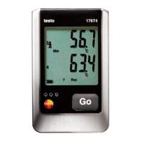
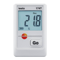
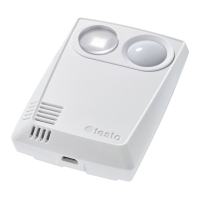
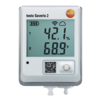
The display, available on models like the Testo 176 T2, Testo 176 T4, Testo 176 H1, and Testo 176 P1, provides real-time information about the operating status and measurement values. It can be switched on or off via the Testo Comfort Software. Various icons and numerical values indicate the current measurement readings, units, alarm thresholds, and battery status. For instance, "Max" and "Min" indicate the highest and lowest saved measurement values, respectively. "Log" shows the number of saved measurement values with alarm violations, while "Act" displays the current intermediate measurement value that is not yet saved.
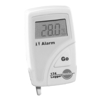
LED indicators provide additional visual feedback on the device's status. A red LED flashing once every 10 seconds indicates remaining battery capacity below 30 days, twice for below 10 days, and three times for an empty battery. Three red flashes when pressing the button signify that a limiting value has been exceeded or fallen short of. Yellow LED flashes indicate changes in mode (e.g., from Wait-mode to Rec-mode) or that the instrument is in Rec-mode. Green LED flashes indicate Wait-mode or End-mode. A sequence of red, yellow, and green LED flashes signals that a battery has been inserted and the capacitor is charging.
The Testo 176 data loggers are designed for ease of use, from initial setup to data retrieval.
Maintaining the Testo 176 data loggers primarily involves battery replacement and cleaning.
| Type | Temperature and Humidity Data Logger |
|---|---|
| Resolution Temperature | 0.1 °C |
| Resolution Humidity | 0.1 %RH |
| Battery Life | Up to 8 years |
| Interface | USB |
| Dimensions | 103 x 63 x 33 mm |
| Protection Class | IP65 |
| Temperature Range | -20 to +70 °C |
| Humidity Range | 0 to 100 %RH |
| Accuracy Temperature | ±0.2 °C |
| Memory | 2 million readings |
| Channels | 1 (Temperature and Humidity) |