4 Product description
24
Status displays during operation
Briefly press the connect button on the rear of the probe once and
the LED shows the status of the connection to the Saveris base.
Representation Explanation
Flashing 3 x green
A very good connection to the Saveris
base exists.
Flashing 2 x green
A good connection to the Saveris base
exists.
Flashing 1 x green
A borderline connection to the Saveris
base exists.
Flashing 3 x red No connection to the Saveris base exists.
Pos: 37 /TD/Produk tbeschreibung/ Übersicht/testo Saver is/02 Ethernet-Füh ler/00 Ethernet-Fühl er @ 1\mod_119755572882 8_79.docx @ 6366 @ 5 @ 1
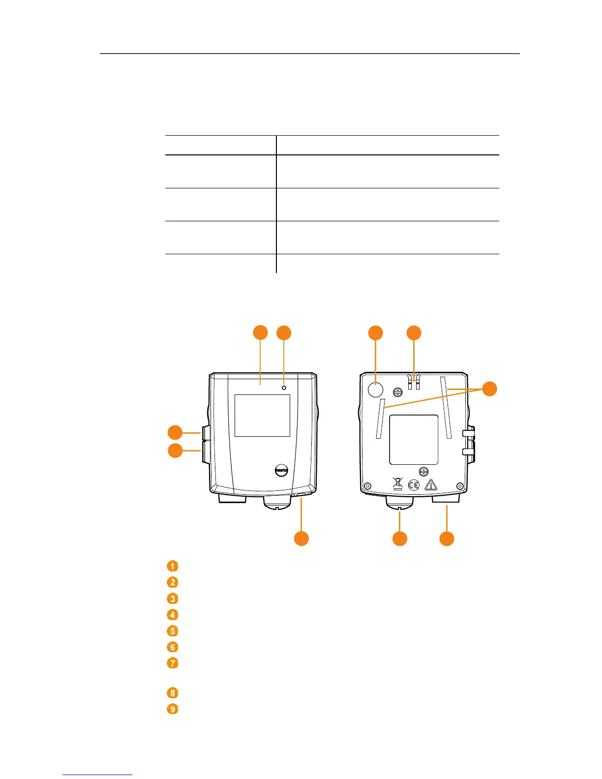
4.4. Saveris Ethernet probes
Pos: 38 /TD/Produk tbeschreibung/ Übersicht/testo Saver is/02 Ethernet-Füh ler/02 Ethernet-Fühl er @ 1\mod_119755573006 2_79.docx @ 6386 @ 2 @ 1
Display for showing the reading and transmission information.
LED for status display.
Connect button.
Catch for the wall bracket.
Guide rails for the wall bracket.
Input for external probes.
Input for external 24 V AC/DC power supply.
M1.6 x 1.5 cable coupling
Input for Ethernet interface.
Input for service interface.
 Loading...