~~------------------
~
945423-9701
Figure
1-1
1-2
1-3
1-4
1-5
1-6
1-7
2-1
2-2
2-3
24
2-5
2-6
3-1
3-2
3-3
34
3-5
3-6
3-7
3-8
3-9
4-1
4-2
4-3
44
Table
1-1
2-1
2-2
2-3
LIST
OF
ILLUSTRATIONS
Title
Page
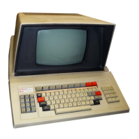
Model 911 Video Display Terminal. . . . . . . . . . . . . . . . . . . . . . . . . . . . . . . . . . . . . . . . . .
1-2
Model 911 VDT Standard Configuration . . . . . . . . . . . . . . . . . . . . . . . . . . . . . . . . . . . . . .
1-3
Major Terminal System Components
.........................................
1-4
Model 911 VDT Controller Block Diagram. . . . . . . . . . . . . . . . . . . . . . . . . . . . . . . . . . . . .
14
United States Standard Keyboard Arrangement.
.................................
1-6
United States Model 911 VDT Displayed Character Set,
Including Graphics Symbols
............................................
1-8
Model 911 VDT International Displayed Characters
..............................
.1-10
Terminal
Physical Dimensions
......................
:
......................
2-1
Model 911 Video Display and Keyboard Shipping
Container.
. . . . . . . . . . . . . . . . .
..
....
24
Keyboard Shipping Container
.............................................
2-5
Basic Terminal Kit
.....................................................
2-7
Model 911 VDT Kit
Cabling Configurations
....................................
2-8
Typical Model 911 VDT
Controller Board
.....................................
2-11
Computer Input Bit Assignments for Terminal a
.................................
3-2
Computer Input Bit Assignments for Terminal 1
.................................
3-3
Displayed
Character Positions
.............................................
3-5
Computer
Output
Bit Assignments for Terminal O
................................
3-7
Computer
Output
Bit Assignments for Terminal 1
................................
3-8
Keyboard
Showing Lowercase Mode Character Positions and
Hexadecimal
Codes
.................................................
.3-14
Keyboard Showing Uppercase Mode Character Positions and
Hexadecimal
Codes
.................................................
.3-14
Keyboard
Showing Control Character Positions and
Hexadecimal
Codes
..................................................
3-14
Keyboard
Showing Shift Mode Character Positions and
Hexadecimal
Codes
.................................................
.3-15
United States Model 911 Keyboard
..........................................
4-2
Display
Unit Control Panel
...............................................
4-3
Data Indicator Locations
................................................
4-3
Data Indicators
Sample Pattern
............................................
44
LIST
OF
TABLES
Title Page
VDT Display Characteristics . . . . . . . . . . . . . . . . . . . . . . . . . . . . . . . . . . . . . . . . . . . . . .
1-5
Terminal Site Installation Requirements
......................................
2-2
VDT
Controller Standard Configurations
......................................
2-10
Addresses Assigned to
CRU Expansion Chassis
..................................
2-11
vii
Digital
Systems
Division

 Loading...