User’s Guide
DRV8316xEVM Evaluation Module
ABSTRACT
This document is provided with the DRV8316xEVM customer evaluation module (EVM) as a supplement to the
DRV8316 data sheet (DRV8316 4.5-V to 35-V Three-Phase Smart Gate Driver). This user's guide details the
hardware implementation of the EVM and how to setup and power the board.
Note
The EVM is populated and configured for the DRV8316R (SPI variant) device by default. To configure
the EVM for the DRV8316T (Hardware variant), please see Section 4.1.1.
Table of Contents
1 Cautions and Warnings..........................................................................................................................................................3
2 Introduction.............................................................................................................................................................................4
3 Quick Start Guide....................................................................................................................................................................5
4 Hardware and Software Overview.........................................................................................................................................6
4.1 LEDs, Switches, and Jumpers........................................................................................................................................... 6
4.2 Hardware Connections Overview – DRV8316xEVM + LAUNCHXL-F280049C.............................................................. 12
4.3 Connection Details........................................................................................................................................................... 13
4.4 Interfacing DRV8316xEVM and LAUNCHXL-F280049C LaunchPad
™
.......................................................................... 16
5 Hardware Setup.................................................................................................................................................................... 18
6 Firmware and GUI Application.............................................................................................................................................19
6.1 C2000
™
InstaSPIN
™
Universal GUI.................................................................................................................................19
6.2 Motor Identification...........................................................................................................................................................20
6.3 Sensorless-FOC Commutation ....................................................................................................................................... 22
6.4 Torque and Speed Control............................................................................................................................................... 22
6.5 SPI Communication (DRV8316R only)............................................................................................................................ 23
7 DRV8316xEVM Schematics..................................................................................................................................................24
8 Revision History................................................................................................................................................................... 27
List of Figures
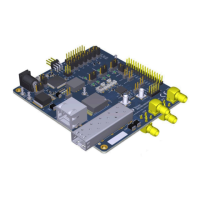
Figure 2-1. DRV8316xEVM PCB Layout..................................................................................................................................... 4
Figure 4-1. DRV8316xEVM LEDs................................................................................................................................................7
Figure 4-2. User-Selectable Jumpers and DNP Components on Top Side of DRV8316xEVM...................................................9
Figure 4-3. User-Selectable Jumpers and DNP Components on Bottom Side DRV8316xEVM............................................... 10
Figure 4-4. Resistor Divider Settings (R37-R46) and Resistors to Disable SPI (R9-R12)......................................................... 11
Figure 4-5. Major DRV8316xEVM Hardware Blocks................................................................................................................. 13
Figure 4-6. Connections From Motor to DRV8316xEVM...........................................................................................................14
Figure 4-7. DRV8316xEVM on Headers J1/J3 and J2/J4 of LaunchPad
™
and Micro-USB Plugged Into LaunchPad
™
.......... 15
Figure 5-1. Bottom Silk Screen Shows Names of Pins When Using an External MCU.............................................................18
Figure 6-1. C2000
™
InstaSPIN
™
Universal GUI for DRV8316xEVM.........................................................................................19
Figure 6-2. C2000
™
InstaSPIN
™
Universal GUI Downloading Program................................................................................... 20
Figure 6-3. Motor Identification Using the DRV8316xEVM InstaSPIN
™
GUI............................................................................ 21
Figure 6-4. Sensorless Sinusoidal Commutation Using the DRV8316xEVM InstaSPIN
™
GUI................................................. 22
Figure 6-5. SPI Communication Using the DRV8316xEVM InstaSPIN
™
GUI........................................................................... 23
Figure 7-1. Main Supply, Reverse Polarity Protection, and Pi Filter Schematic........................................................................ 24
Figure 7-2. Voltage Sense and Protection Schematic............................................................................................................... 24
Figure 7-3. Connectors and Interface Schematic...................................................................................................................... 25
Figure 7-4. DRV8316 3-phase BLDC Motor Driver Schematic..................................................................................................25
Figure 7-5. VREF / ILIM Schematic........................................................................................................................................... 26
Figure 7-6. 3.3V Integrated Buck Regulator Schematic............................................................................................................ 26
www.ti.com Table of Contents
SLVUBZ9B – DECEMBER 2020 – REVISED AUGUST 2021
Submit Document Feedback
DRV8316xEVM Evaluation Module 1
Copyright © 2021 Texas Instruments Incorporated