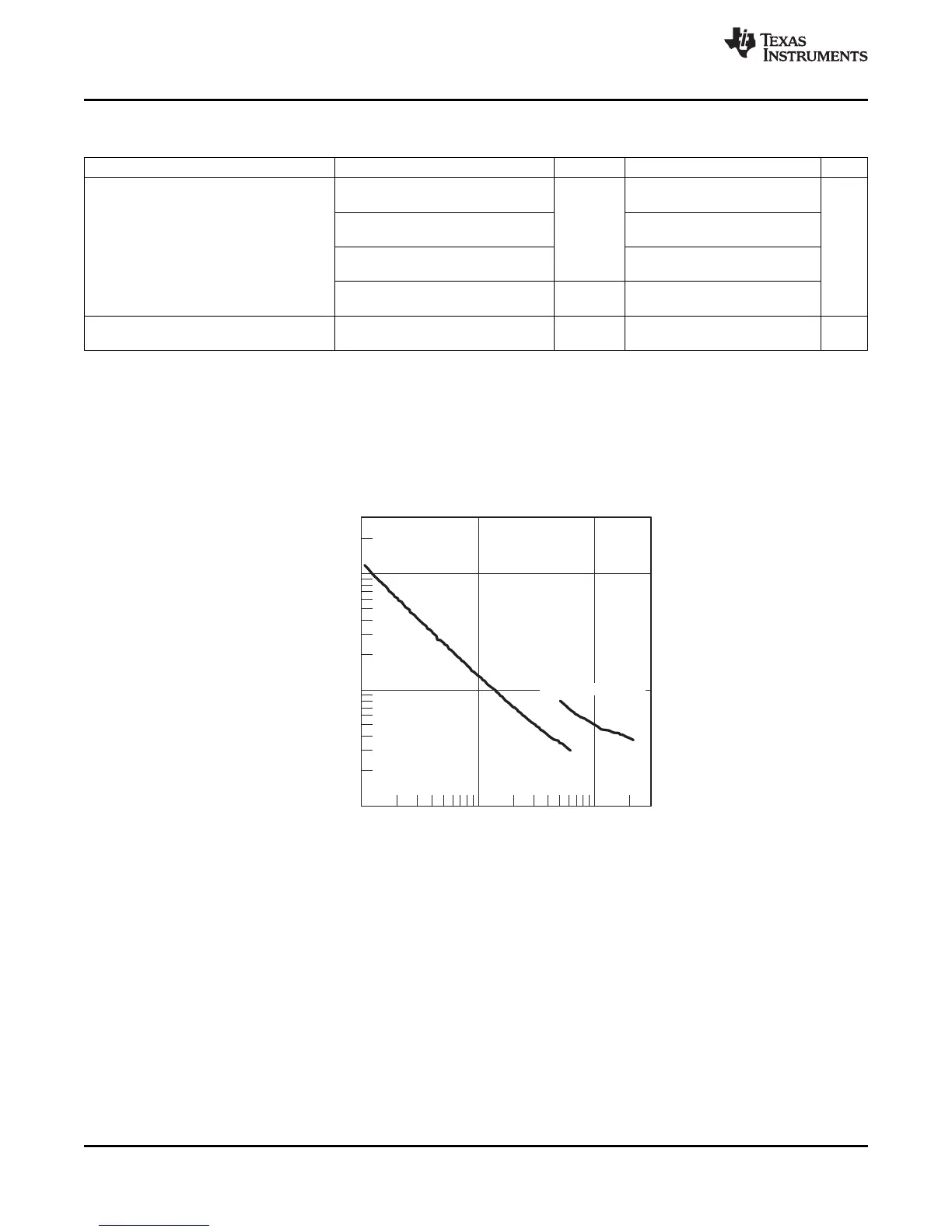
DCO Frequency − MHz
0.10
1.00
10.00
0.10 1.00 10.00
RSELx = 0 to 11
DCO Wake Time − µs
RSELx = 12 to 15
MSP430F23x
MSP430F24x(1)
MSP430F2410
SLAS547I –JUNE 2007–REVISED DECEMBER 2012
www.ti.com
Wake-Up From Lower-Power Modes (LPM3/4)
over recommended ranges of supply voltage and operating free-air temperature (unless otherwise noted)
PARAMETER TEST CONDITIONS V
CC
MIN TYP MAX UNIT
BCSCTL1 = CALBC1_1MHZ,
2
DCOCTL = CALDCO_1MHZ
BCSCTL1 = CALBC1_8MHZ,
2.2 V, 3 V 1.5
DCOCTL = CALDCO_8MHZ
DCO clock wake-up time
t
DCO,LPM3/4
µs
from LPM3/4
(1)
BCSCTL1 = CALBC1_12MHZ,
1
DCOCTL = CALDCO_12MHZ
BCSCTL1 = CALBC1_16MHZ,
3 V 1
DCOCTL = CALDCO_16MHZ
CPU wake-up time from 1 / f
MCLK
+
t
CPU,LPM3/4
LPM3/4
(2)
t
Clock,LPM3/4
(1) The DCO clock wake-up time is measured from the edge of an external wake-up signal (for example, a port interrupt) to the first clock
edge observable externally on a clock pin (MCLK or SMCLK).
(2) Parameter applicable only if DCOCLK is used for MCLK.
Typical Characteristics - DCO Clock Wake-Up Time From LPM3/4
CLOCK WAKE-UP TIME FROM LPM3
vs
DCO FREQUENCY
Figure 18.
46 Submit Documentation Feedback Copyright © 2007–2012, Texas Instruments Incorporated
 Loading...


