MSP430F23x
MSP430F24x(1)
MSP430F2410
SLAS547I –JUNE 2007–REVISED DECEMBER 2012
www.ti.com
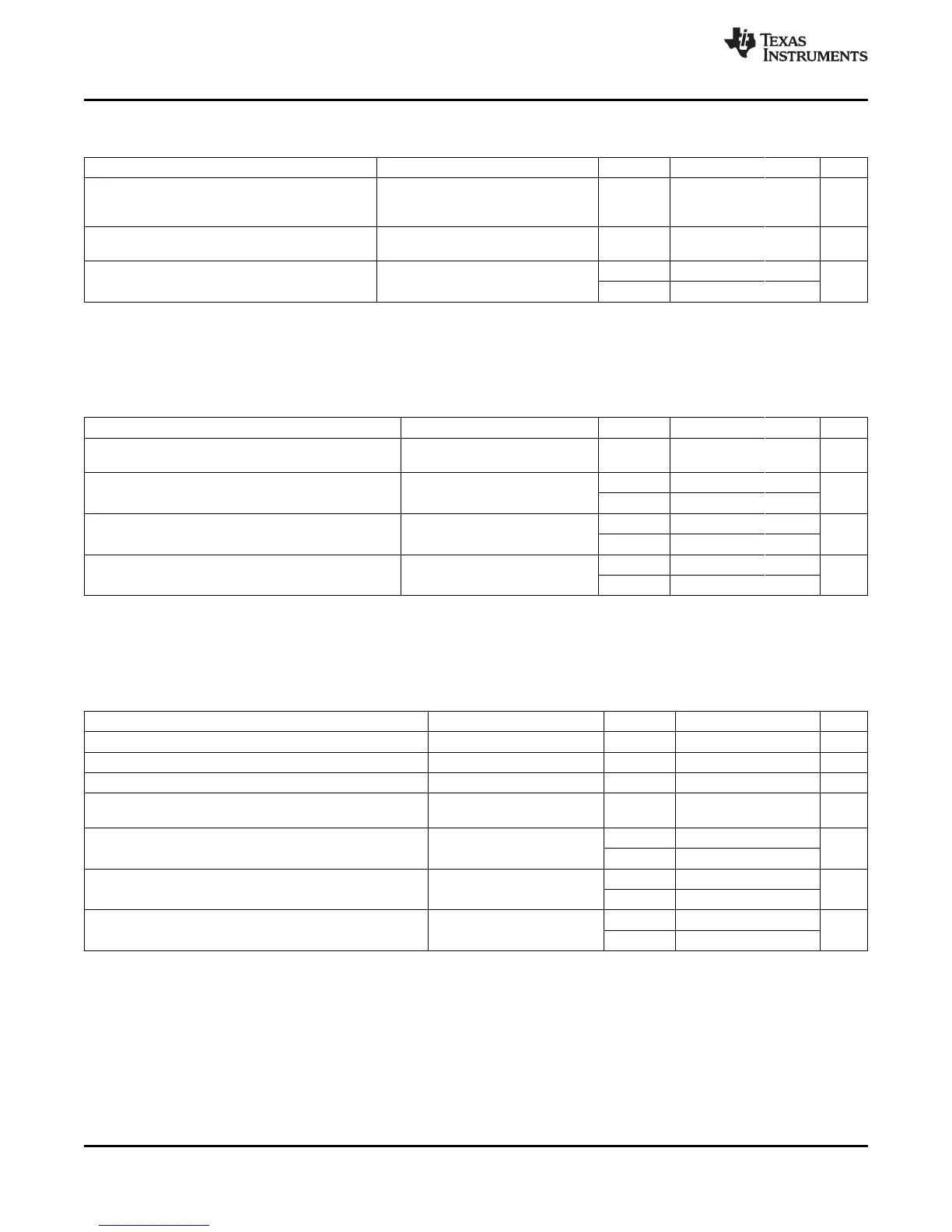
USCI (UART Mode)
over recommended ranges of supply voltage and operating free-air temperature (unless otherwise noted)
PARAMETER CONDITIONS V
CC
MIN TYP MAX UNIT
Internal: SMCLK, ACLK
f
USCI
USCI input clock frequency External: UCLK f
SYSTEM
MHz
Duty cycle = 50% ± 10%
BITCLK clock frequency
f
BITCLK
2.2 V, 3 V 1 MHz
(equals baud rate in MBaud)
(1)
2.2 V 50 150
t
τ
UART receive deglitch time
(2)
ns
3 V 50 100
(1) The DCO wake-up time must be considered in LPM3/4 for baudrates above 1 MHz.
(2) Pulses on the UART receive input (UCxRX) shorter than the UART receive deglitch time are suppressed.
USCI (SPI Master Mode)
(1)
over recommended ranges of supply voltage and operating free-air temperature (unless otherwise noted)
(see Figure 27 and Figure 28)
PARAMETER TEST CONDITIONS V
CC
MIN TYP MAX UNIT
SMCLK, ACLK
f
USCI
USCI input clock frequency f
SYSTEM
MHz
Duty cycle = 50% ± 10%
2.2 V 110
t
SU,MI
SOMI input data setup time ns
3 V 75
2.2 V 0
t
HD,MI
SOMI input data hold time ns
3 V 0
2.2 V 30
UCLK edge to SIMO valid,
t
VALID,MO
SIMO output data valid time ns
C
L
= 20 pF
3 V 20
(1) f
UCxCLK
= 1/2t
LO/HI
with t
LO/HI
≥ max(t
VALID,MO(USCI)
+ t
SU,SI(Slave)
, t
SU,MI(USCI)
+ t
VALID,SO(Slave)
).
For the slave's parameters t
SU,SI(Slave)
and t
VALID,SO(Slave)
, see the SPI parameters of the attached slave.
USCI (SPI Slave Mode)
(1)
over recommended ranges of supply voltage and operating free-air temperature (unless otherwise noted)
(see Figure 29 and Figure 30)
PARAMETER TEST CONDITIONS V
CC
MIN TYP MAX UNIT
t
STE,LEAD
STE lead time, STE low to clock 2.2 V, 3 V 50 ns
t
STE,LAG
STE lag time, Last clock to STE high 2.2 V, 3 V 10 ns
t
STE,ACC
STE access time, STE low to SOMI data out 2.2 V, 3 V 50 ns
STE disable time, STE high to SOMI high
t
STE,DIS
2.2 V, 3 V 50 ns
impedance
2.2 V 20
t
SU,SI
SIMO input data setup time ns
3 V 15
2.2 V 10
t
HD,SI
SIMO input data hold time ns
3 V 10
2.2 V 75 110
UCLK edge to SOMI valid,
t
VALID,SO
SOMI output data valid time ns
C
L
= 20 pF
3 V 50 75
(1) f
UCxCLK
= 1/2t
LO/HI
with t
LO/HI
≥ max(t
VALID,MO(Master)
+ t
SU,SI(USCI)
, t
SU,MI(Master)
+ t
VALID,SO(USCI)
).
For the master's parameters t
SU,MI(Master)
and t
VALID,MO(Master)
see the SPI parameters of the attached slave.
54 Submit Documentation Feedback Copyright © 2007–2012, Texas Instruments Incorporated
 Loading...


