Stellaris® Stepper Motor RDK User’s Manual
November 4, 2009 23
Also on this page are several LED status indicators, a simple reset circuit, and on-board user
interface. The speed/position potentiometer's value is read by the microcontroller's ADC. Because
the ADC's input span is 0-3 V, a resistor (R14) is used to pad the potentiometer voltage.
The microcontroller's on-chip analog comparator provides an over-current trip function. Diodes D2
and D3 gate the greater of the two motor coil currents into an R/C network which connects to the
inverting comparator input. Inside the microcontroller, this level is compared to a programmable
voltage reference. An interrupt will be generated in the event of an over-current condition allowing
the software to quickly shut-down the power stage.
Output Power Stage (Schematic Page 3)
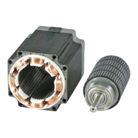
The power stages on schematic pages 3 and 4 are identical. One power stage is used for each of
the two coils in the bipolar stepper motor.
The power stage consists primarily of a MOSFET H-bridge and associated gate drivers. The
H-bridge allows the microcontroller to control the magnitude and polarity of the current in the
motor. Each H-bridge has three logic control signals. PH_x1 and PH_x2 control whether the
high-side or low-side switch is on. A common active-low enable signal can force all switches off.
To turn on the high-side MOSFETs, the gate voltage must be driven higher than the source. This is
achieved by using a gate driver and a flying-[or bootstrap] capacitor. Using Phase A1 as an
example: When the low-side MOSFET (Q4) is ON, diode D7 is forward biased and capacitors C16
and C18 charge to almost 15 V. In turn, this charge allows the high-side MOSFET (Q3) to be
turned on by the high-side gate driver. As the high-side MOSFET turns on, its source voltage rises
taking the negative terminal of the flying capacitor along with it. The capacitor is sized to maintain
a high-side supply voltage of at least HV
DC
+ 12.5 V during the ON state. If the capacitor
discharges below 11.3 V (typ), the SPM's under-voltage lock-out circuit activates to prevent the
MOSFET from moving outside its safe operating area (SOA).
Two 100m
Ω resistive shunts provide 100 mV/A current sensing. The resultant voltage is fed into
an operation amplifier and into the comparator circuit on Page 2.
Page 3 also shows a linear hall-effect sensor for positional feedback. This circuit is not presently
populated.
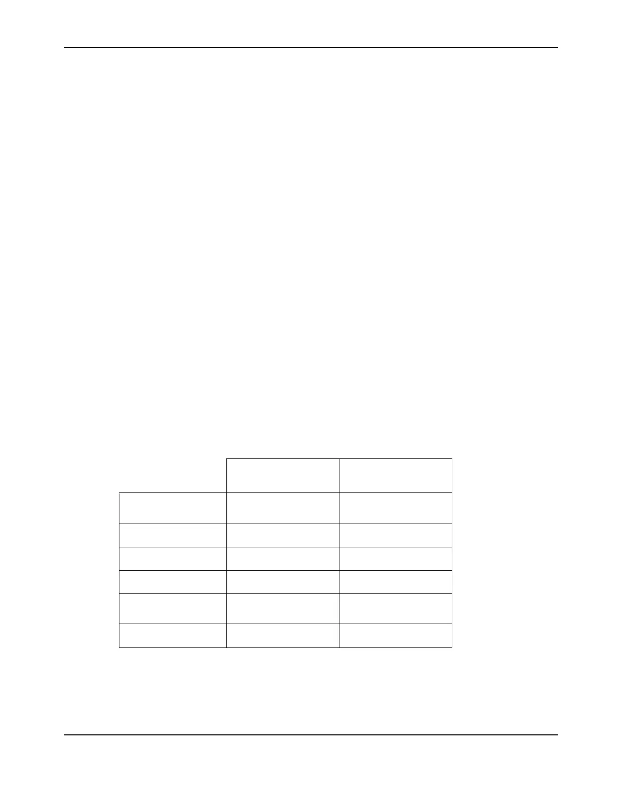
Table 3-1. Current Monitoring Circuits
Microcontroller
Comparator
Microcontroller ADC
Function
Software programmable
current trip
Measurement of phase
current amplitude
Amplifier Gain
n/a 11
Resolution
137.5 mV (1.375 A) 10 bits
Scale
100 mV/A – 0.15 V 1 bit = 2.67 mA
Trip Threshold (typ.)
Programmable
reference
In software
Trip Speed (typ.)
<10 us Software-dependent