Stellaris® Stepper Motor RDK User’s Manual
November 4, 2009 19
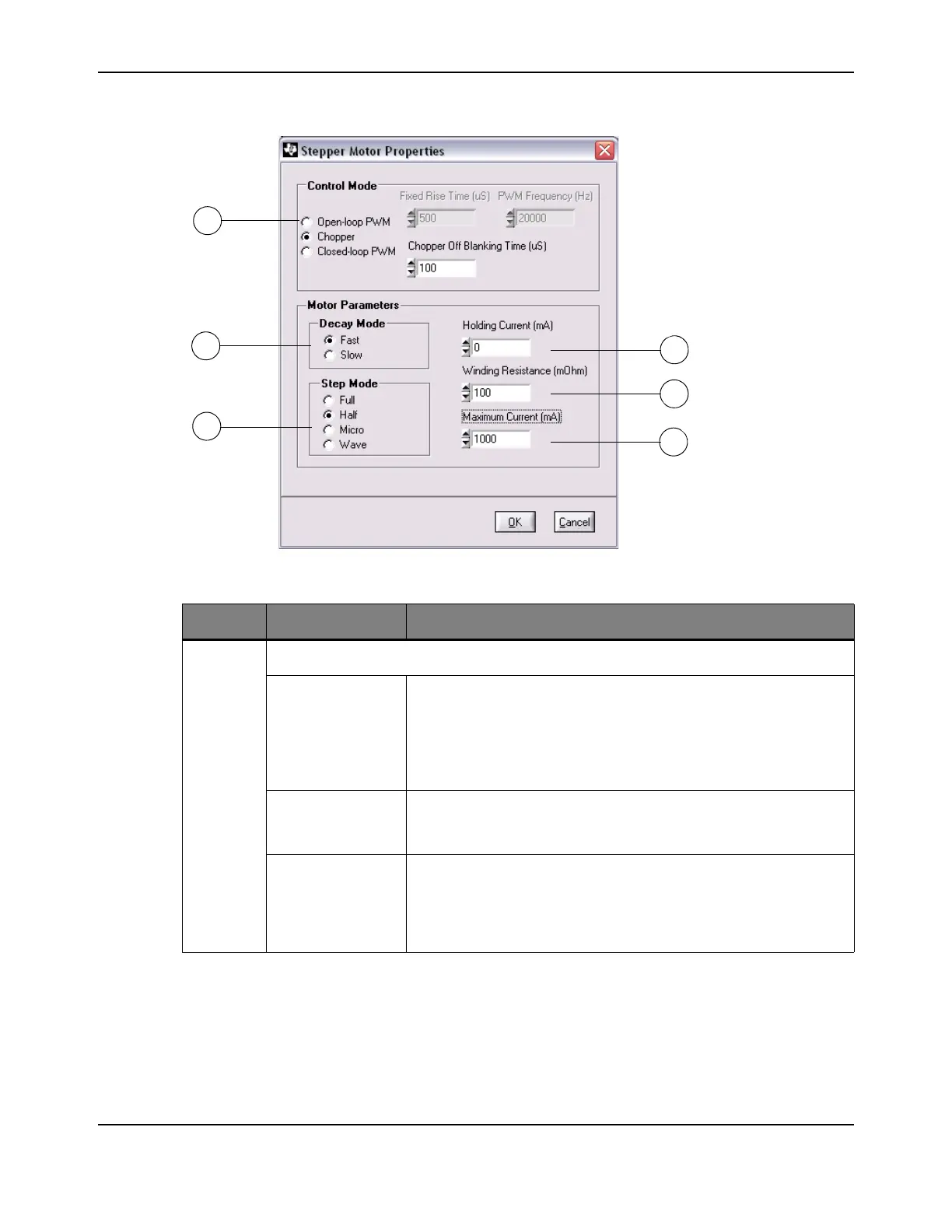
Figure 2-3. Configuration Window
Table 2-2. Description of Configuration Controls
Item No. Name Description
1
Control Mode
Open-loop PWM In Open-loop PWM control mode, the firmware sets the PWM duty
cycle to a value that corresponds to the desired current. The duty
cycle is calculated based on the winding resistance and the bus
voltage. There is no actual measurement of the winding current. In
PWM mode, the Fixed Rise Time parameter can also be used (see
Fixed Rise Time).
Chopper In Chopper control mode, the microcontroller firmware monitors the
current flowing in the winding, and switches the voltage to the winding
on and off in order to keep the current at the desired value.
Closed-loop PWM In Closed-loop PWM control mode, the firmware sets the PWM duty
cycle based on the measurement of the current flowing in the winding.
If the current is below the desired setting, then the PWM duty cycle
will be set to a large value, and is reduced as the measured current
approaches the desired value.