Hardware Description
22 November 4, 2009
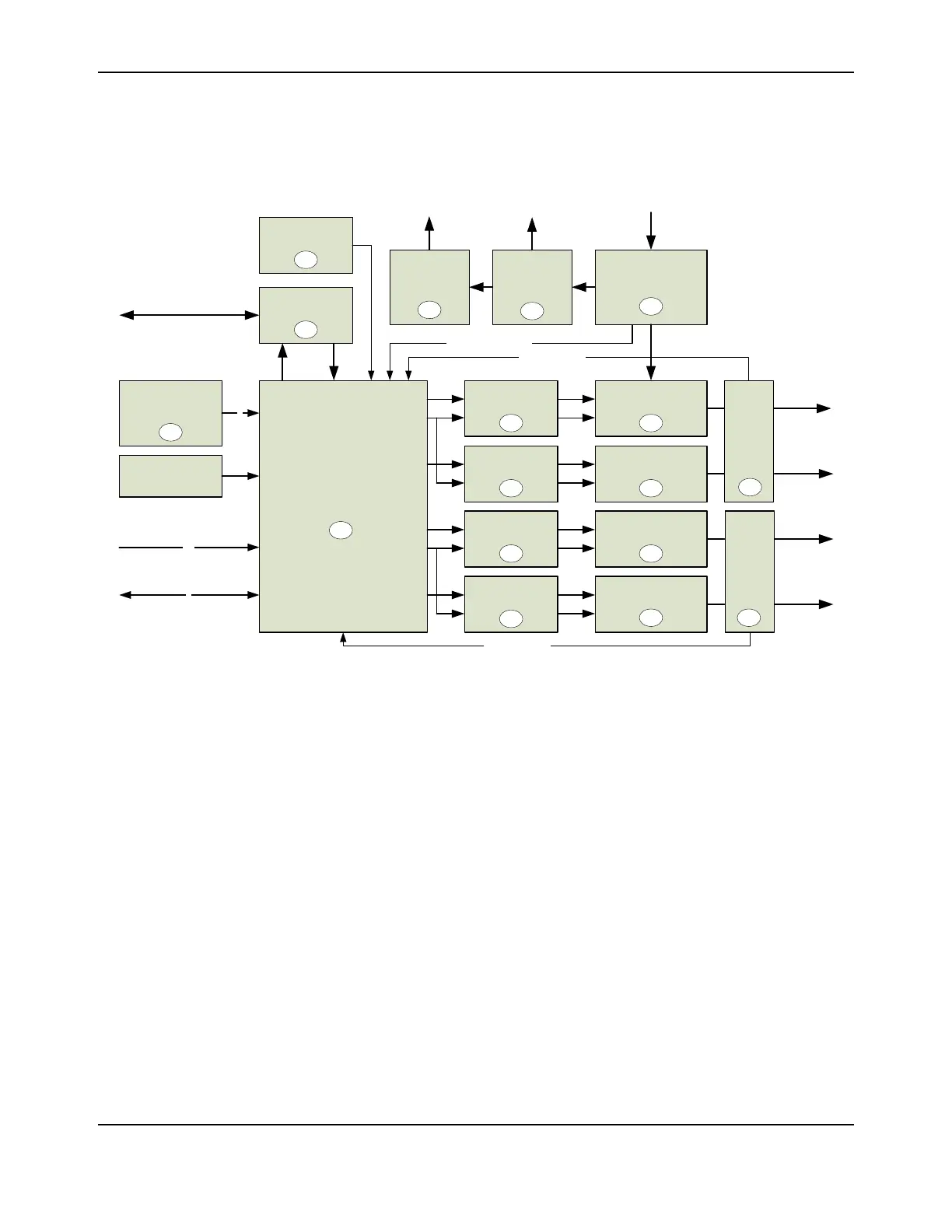
Block Diagram
Figure 3-2. Block Diagram
Functional Description
Stepper motor controls normally use a dedicated controller chip to implement a chopper-based
drive stage. The microcontroller, if present, is there to manage position control and send step
pulses to the controller. The RDK implements all of this functionality in the Stellaris microcontroller.
One of the benefits of a software implementation is that the rest of the circuit is simple and can use
standard power semiconductors. This section contains a detailed description of the RDK’s
operation. See Appendix B, “Schematics” starting on page 33 for more details.
Microcontroller (Schematic Pages 1-2)
At the core of the Stepper Motor RDK is a Stellaris LM3S617 microcontroller. This part has a
peripheral set optimized for motor control, including 6 high-speed ADC channels, a motor control
PWM block, and an analog comparator.
The RDK has a 20-pin ARM JTAG port for programming and debugging. A standard debug
interface can be connected to this header (J1).
Unallocated GPIO signals from the microcontroller are routed to pads labeled P1-P19. Several
peripheral blocks are available for external use including SPI and UART1. The I/O pads are on a
0.1" grid to allow standard headers to be installed.
DC Bus Capacitors
Switching
Power Supply
Stellaris
Microcontroller
High/Low Side
Gate Driver
MOSFET Pair
High/Low Side
Gate Driver
High/Low Side
Gate Driver
Linear Hall-effect
Sensor
Motor A1
9-80V DC IN
+3.3V
J
A
B
B
B
Current
Sense
Ampl.
D
TxD
RxD
DC Voltage Sense
/
4
JTAG/SWD
USB to Serial
USB
High/Low Side
Gate Driver
B
MOSFET Pair
MOSFET Pair
MOSFET Pair
Current
Sense
Ampl.
D
Motor A2
Motor B1
Motor B2
/
14
Spare GPIO
Potentiometer
(Speed/Pos Adjust)
/
2
Mode
Push Switch
Switching
Power Supply
+15V
C
C
C
C
F
H
I
G
E
Current Sense
Current Sense