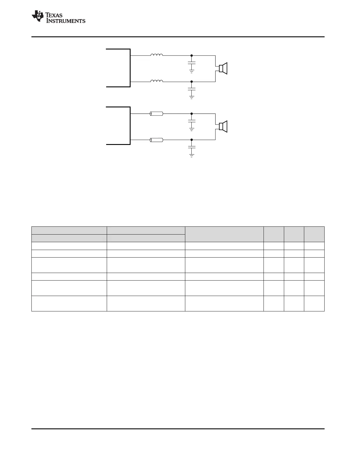
OUTP
OUTN
10 µH
L1
10 µH
L2
C2
C3
0.68 µF
0.68 µF
OUTP
OUTN
Ferrite
Chip Bead
1 nF
1 nF
Ferrite
Chip Bead
4 - 8W W
4 - 8W W
23
TPA3116D2
,
TPA3118D2
,
TPA3130D2
www.ti.com
SLOS708G –APRIL 2012–REVISED DECEMBER 2017
Product Folder Links: TPA3116D2 TPA3118D2 TPA3130D2
Submit Documentation FeedbackCopyright © 2012–2017, Texas Instruments Incorporated
Figure 35. TPA31xxD2 Output Filters
7.3.16 AM Avoidance EMI Reduction
To reduce interference in the AM radio band, the TPA3116D2 has the ability to change the switching frequency
via AM<2:0> pins. The recommended frequencies are listed in Table 6. The fundamental frequency and its
second harmonic straddle the AM radio band listed. This eliminates the tones that can be present due to the
switching frequency being demodulated by the AM radio.
Table 6. AM Frequencies
US EUROPEAN
SWITCHING FREQUENCY (kHz) AM2 AM1 AM0
AM FREQUENCY (kHz) AM FREQUENCY (kHz)
522-540
540-917 540-914 500 0 0 1
917-1125 914-1122 600 (or 400)
0 1 0
0 0 0
1125-1375 1122-1373 500 0 0 1
1375-1547 1373-1548 600 (or 400)
0 1 0
0 0 0
1547-1700 1548-1701 600 (or 500)
0 1 0
0 0 1
 Loading...