Appendix B
www.ti.com
14
SNAU228–January 2018
Submit Documentation Feedback
Copyright © 2018, Texas Instruments Incorporated
USB2ANY Cable Connections
• Interrupts: INT0, INT1, and INT2
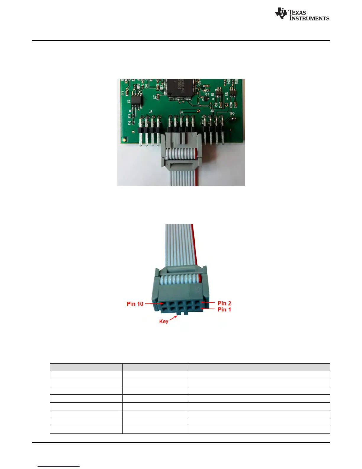
The 10-pin cable is about 6 in long and has a keyed female 10-pin IDC connector on each end. Connect
the cable to the USB2ANY board as Figure 13 shows (note that the key must be facing up, away from the
board).
Figure 13. 10-Pin IDC Cable Connector
The opposite end of the cable is intended to be connected to the EVM or other target device. The red
stripe on the cable indicates pin 1.
Figure 14. 10-Pin IDC Cable Detail
Table 2. 10-pin Cable Pinouts
Schematic Pin Number Cable Pin Number Signals Available
J4-10 1 GPIO7, PWM0, INT2, OW2, OW5
J4-9 2 GPIO6, PWM1, RFFE:SCLK, SPI:CS, INT1, µWIRE:CS, OW1
J4-8 3 GPIO5, SPI:SOMI, UART:RXD, µWIRE:SOMI
J4-7 4 GPIO4, SPI:SIMO, UART:TXD, µWIRE:SIMO
J4-6 5 3.3VEXT
J4-5 6 GND
J4-4 7 GPIO3, PWM2, RFFE:SDATA, INT0
J4-3 8 GPIO2, ES:DOUT, SPI:SCLK, µWIRE:SCLK
 Loading...