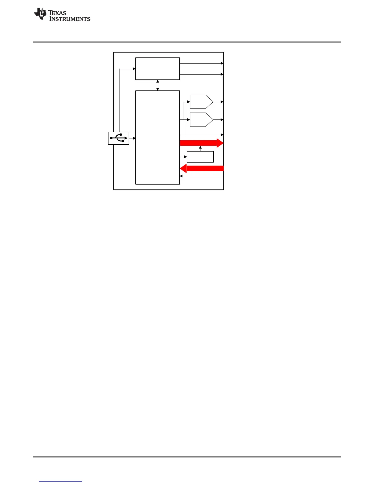
Power Management
(14)
MSP430F5529
Switchable
1
2C pullups
(4)
+3.3 V
+5.0 V
DAC1
DAC2
GPIO, 12C, PWM,
and other interfaces
(shared lines)
Analog Inputs
Ext. V
REF
Copyright © 2017, Texas Instruments Incorporated
www.ti.com
Overview of Hardware Design
5
SNAU228–January 2018
Submit Documentation Feedback
Copyright © 2018, Texas Instruments Incorporated
USB2ANY Interface Adapter
Figure 2. USB2ANY Block Diagram
Figure 3 shows the USB2ANY PCB without the enclosure. One end has three interface connectors that
are typically connected to an EVM (J3, J4, and J5). Connectors J3 and J5 have eight pins and J4 has 10
pins. Most applications will use only J4 because it provides access to the most commonly used interfaces
(see Using the 10-Pin Cable in Connecting the USB2ANY). Alternatively, a 30-pin cable is provided that
connects to all three connectors (J3, J4, and J5) and provides access to all available interface signals.
 Loading...