Overview of Hardware Design
www.ti.com
6
SNAU228–January 2018
Submit Documentation Feedback
Copyright © 2018, Texas Instruments Incorporated
USB2ANY Interface Adapter
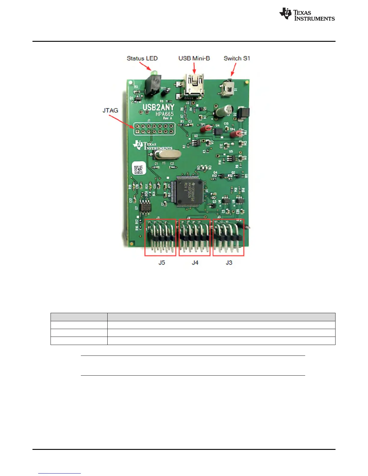
Figure 3. USB2ANY PCB
The Status LED indicates the status of the electronics and firmware, as follows:
Table 1. Status LEDs
LED State Meaning
OFF No power to the board. USB cable may be unplugged.
ON Power is applied and the board is operating normally.
Blinking A hardware, firmware, or USB error occurred. Board must be power-cycled.
NOTE: The LED may also be programmed using the software API to be ON, OFF, or blinking. In
that case, the LED may not indicate the actual status of the electronics or firmware.
Switch S1 is used to put the firmware into bootstrap loader (BSL) mode. The BSL mode is used to load or
update the USB2ANY firmware and is entered whenever the board is powered-up while Switch S1 is
depressed.
The USB Mini-B (J2) connector is used to connect the USB2ANY to the host computer. A cable with a
USB Mini-B connector on one end and a USB A connector on the other end is provided with the
USB2ANY.
The JTAG connector (J1) is used only for firmware development and is normally not populated with a
physical connector.
 Loading...