882 and 882CB Hydraulic Benders
Greenlee / A Textron Company 4455 Boeing Dr. • Rockford, IL 61109-2988 USA • 815-397-7070
10
Laying Out Bends (cont’d)
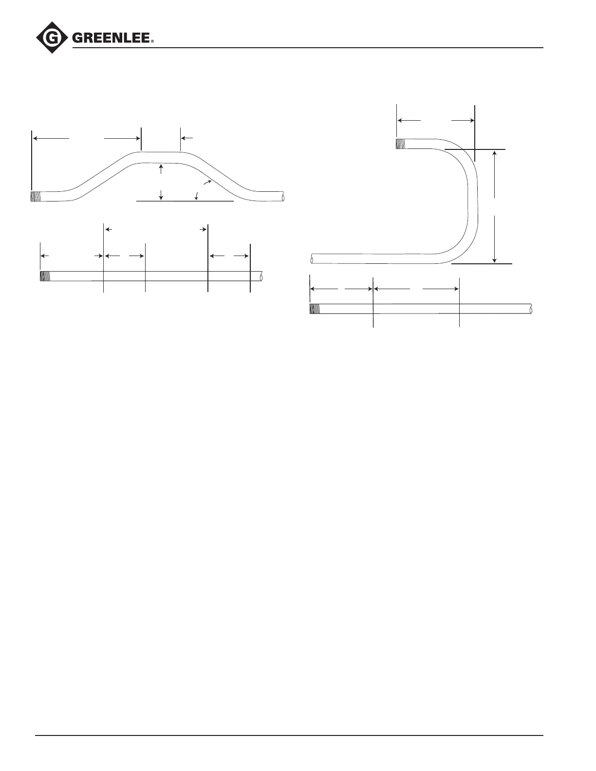
Four-Bend Saddle
BENDING
MARK 2
BENDING
MARK 1
BENDING
MARK 4
BENDING
MARK 3
LENGTH – Z
LENGTH
STRAIGHT
SECTION
L1 L1
ANGLE
HEIGHT
L2 + STRAIGHT SECTION
U-Bends
LENGTH
HEIGHT
Y L1
BENDING
MARK 1
BENDING
MARK 2
1. Select the size and type of conduit to be bent.
Measure the height of the obstruction, the dis-
tance labeled LENGTH, and the distance labeled
STRAIGHT SECTION. Select the angle to be used.
2. Find the chart that corresponds to the type and size
of conduit selected in Step 1.
3. Under the column labeled ANGLE, nd the angle of
bend needed. Find the row labeled Z. In the row at
the top of the page, nd the height (H) of the offset.
The number shown at this intersection is Z. Subtract
Z from the LENGTH. Place the rst bending mark
this distance from the end of the conduit.
4. In the same column, nd the row labeled L1. Place
the second bending mark L1 inches from the rst
bending mark.
5. In the same column, nd the row labeled L2. Add L2
to the STRAIGHT SECTION. Place the third bending
mark this distance from the rst bending mark.
6. Make the nal bending mark L1 inches from the
third bending mark.
7. See the bending instructions.
1. Select the size and type of conduit to be bent.
Determine the LENGTH and the HEIGHT.
2. Find the chart that corresponds to the type and size
of conduit selected in Step 1.
3. Under the column labeled ANGLE, nd 90°.
4. Find the row labeled Y. In the row at the top of the
page, nd the height (H) that corresponds to the
LENGTH. The number shown at this intersection is
the dimension Y. Place the bending mark Y inches
from the end of the conduit.
5. Find the row labeled L1, and go to the right to nd
the height (H) that corresponds to the HEIGHT. The
number shown at this intersection is the dimension
L1. Place the second bending mark L1 inches from
the rst mark.
6. See the bending instructions.