882 and 882CB Hydraulic Benders
Greenlee / A Textron Company 4455 Boeing Dr. • Rockford, IL 61109-2988 USA • 815-397-7070
8
Laying Out Bends
The following drawings and bending charts are intended
to provide the information necessary to accomplish the
most common types of bends. The “Special Bending
Information Chart” contains information for the most
commonly needed bending dimensions.
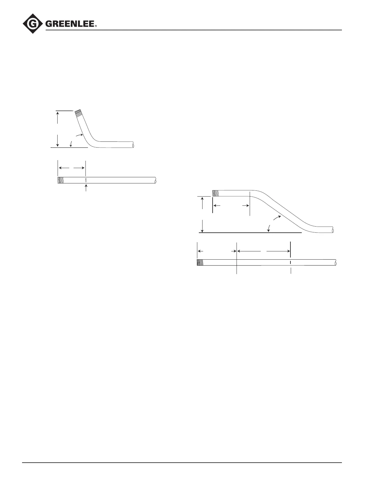
Stubs
MARK
Y
HEIGHT
ANGLE
1. Select the size and type of conduit to be bent.
Determine the height of stub and the angle of bend.
2. Find the chart that corresponds to the type and size
of conduit selected in Step 1.
3. Under the column labeled ANGLE, nd the angle of
bend.
4. Find the row labeled Y. In the row at the top of the
page, nd the height (H) of the stub. The number
shown at this intersection is the dimension Y. Place
the bending mark Y inches from the end of the
conduit.
5. See the bending instructions.
Offset
An offset is used to route the conduit around an
obstruction. To make an offset, two equal bends are
required. The distance between the two bends is the
center-to-center distance. This is represented by L1 in
the bending tables.
When working past an obstruction, it is necessary to
determine the location of the rst bend. The center-to-
center distance is then used to nd the location of the
second bend.
When working toward an obstruction, it is necessary to
determine the location of the second bend. The center-
to-center distance is then used to nd the location of
the rst bend.
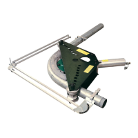
Offsets: Working Past an Obstruction
BENDING
MARK 2
BENDING
MARK 1
LENGTH – X
LENGTH
L1
ANGLE
HEIGHT
START OF
FIRST BEND
1. Select the size and type of conduit to be bent.
Measure the height of the obstruction and the dis-
tance labeled LENGTH. Select the angle to be used.
2. Find the chart that corresponds to the type and size
of conduit selected in Step 1.
3. To the right of the size and type of conduit, nd the
dimension labeled X. Subtract X from LENGTH.
Place the rst bending mark (Bending Mark 1) this
distance from the end of the conduit.
4. Under the column labeled ANGLE, nd the angle
of bend. Find the row labeled L1. In the row at the
top of the page, nd the height (H) of the offset.
The number at this intersection is the dimension L1.
Place the second bending mark (Bending Mark 2)
L1 inches from the rst bending mark.
5. See the bending instructions.