GASOLINE UTILITY VEHICLES
Page 8
Owner’s Manual and Service Guide
Read all of manual to become thoroughly familiar with this vehicle. Pay particular attention to all Notes, Cautions and Warnings
CONTROLS AND INDICATORS
Vehicle controls and indicators consist of:
• key/light switch
• low oil pressure light
• fuel gauge
• direction selector
• choke
• accelerator pedal
• combination service brake and parking (PARK) brake
pedal
• horn
• 12 volt power outlet
• electric lift switch for operation of the dump bed
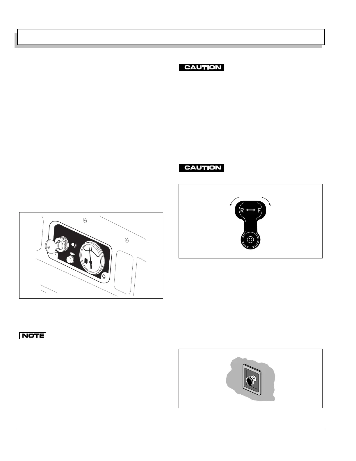
Key/Light Switch
Located on the dash panel, this switch enables the basic
electrical system of the vehicle to be turned on and off by
turning the key. The lights will illuminate only when the
key is moved to the light icon (Ref Fig. 12 on page 8).
When the vehicle is left unattended, the key should be
removed to prevent inadvertent operation of the vehicle.
If the vehicle is equipped with custom accesso-
ries, some accessories may remain operational
with the key switch in the ‘OFF’ position.
Low Oil Pressure Light
A low oil pressure light is located to the right side of the
key/light switch (Ref Fig. 12 on page 8). If oil pressure
drops too low, the oil pressure switch will activate the
light. Check oil level (Ref Fig. 25 on page 16). If oil level
is between ADD and FULL mark on dipstick, a mechani-
cal problem exists within the engine and the vehicle
must not be driven. Contact a local distributor or autho-
rized Branch.
To prevent engine damage, do not operate
engine until oil pressure is corrected.
If oil level is below ADD mark on dipstick, add oil to bring
level to FULL mark. Drive vehicle a short distance and
check oil pressure. If oil light does not come on, continue
to use vehicle.
Fuel Gauge
An electric fuel gauge is located to the right side of the
key/light switch. It indicates the amount of fuel in the
tank. An optional dash mounted low fuel warning light is
available (Ref Fig. 12 on page 8).
Direction Selector
The vehicle must be completely stopped
before moving the direction selector to
prevent component damage.
Located on the seat support panel, this lever permits the
selection of either ‘F’ (forward) or ‘R’ (reverse) (Ref Fig.
13 on page 8). Neutral can be locked at the direction
selector bracket (Refer to page 13). The vehicle should
be left in ‘F’ when unattended.
Choke
Located on the seat support panel, the choke is used to
aid cold starting (Ref Fig. 14 on page 8). See ‘Cold Start-
ing’ (Refer to page 11) for instructions on using the choke
properly.
Fig. 12 Key/Light Switch and Fuel Gauge
OFF
ON
FUEL
F
E
Fig. 13 Direction Selector
Fig. 14 Choke
Forward
Reverse
(Neutral)