GASOLINE UTILITY VEHICLES
Page 9
Owner’s Manual and Service Guide
Read all of manual to become thoroughly familiar with this vehicle. Pay particular attention to all Notes, Cautions and Warnings
Accelerator Pedal
Depressing the accelerator pedal starts the engine.
When the pedal is released, the engine will stop (Ref Fig.
15 on page 9).
If key switch is ‘ON’ and
parking brake is set,
depressing the accelerator
will release the parking brake and cause the vehicle to
move which could result in severe personal injury or
death.
Depressing the accelerator pedal will release the parking
(PARK) brake if it is engaged. This is a feature to assure
the vehicle is not driven with the parking (PARK) brake
engaged. Depressing the accelerator pedal is NOT
the preferred method of releasing the parking brake.
Depressing the bottom of the brake pedal is the
preferred method of releasing the parking
(PARK) brake to assure the longest service life of brake compo-
nents
.
Combination Brake and Parking (PARK)
Brake Pedal
The brake pedal incorporates a parking (PARK) brake
feature (Ref Fig. 15 on page 9). To engage, push down
on the top section of the pedal until it locks in place. The
parking (PARK) brake will release when the service
brake pedal is depressed. Use the BOTTOM section of
the brake pedal to operate the service brake system.
Horn
The horn is an electric powered unit that is activated by a
push button located on the upper floorboard to the left of
the brake pedal (Ref Fig. 15 on page 9).
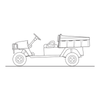
12 Volt Power Outlet
Overuse of accessories may drain the bat-
tery and leave insufficient reserve to start
the vehicle.
A 12 volt power outlet is located to the left side of the key/
light switch (Ref Fig. 16 on page 9). It provides constant
power for accessories equipped with a 12 volt plug.
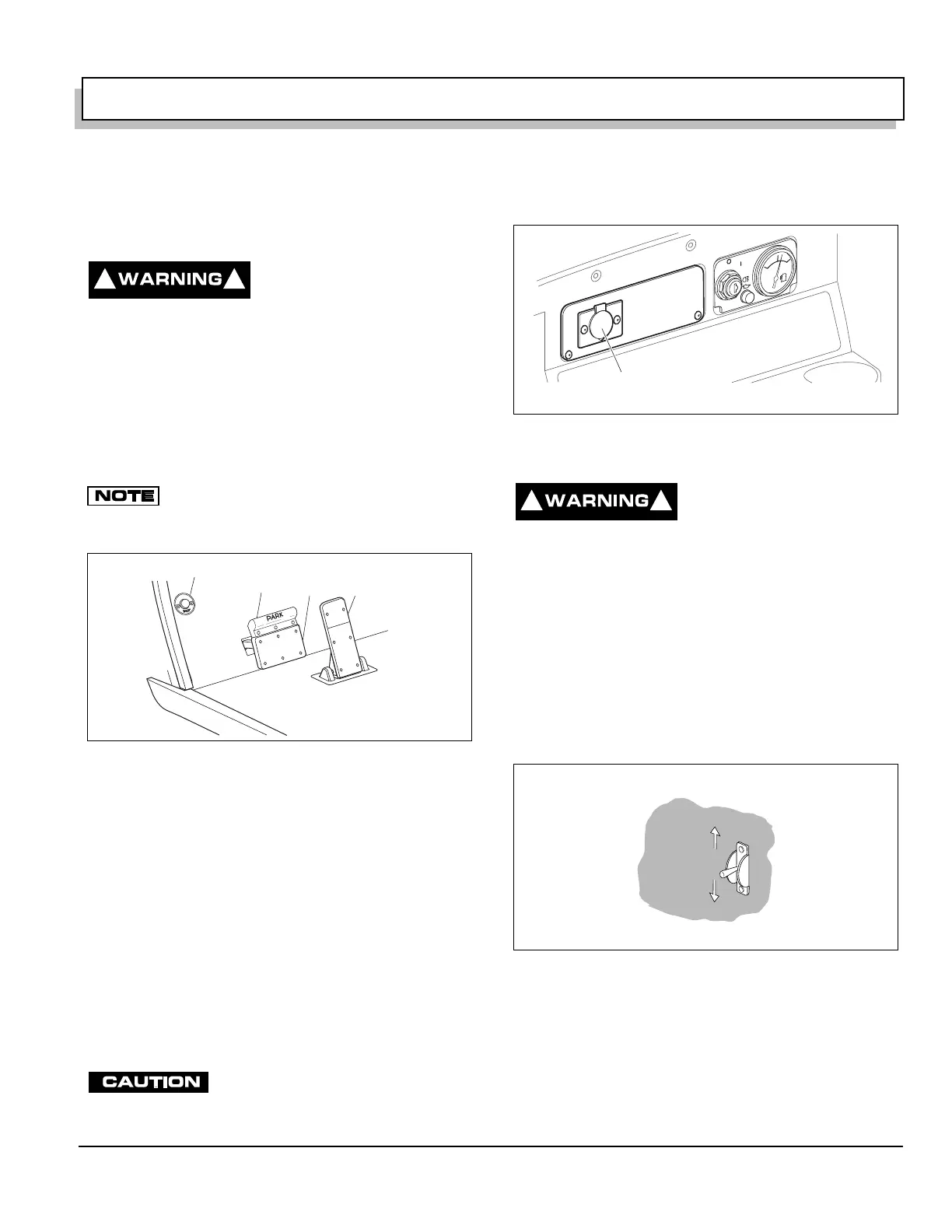
Electric Lift
Exercise caution while oper-
ating the electric lift bed to
insure clothing is not
snagged during lifting or lowering. Severe injury
could result if body parts are caught on or under bed
while moving.
Do not back up to a drop off, such as a loading dock
or ravine. Misjudgment or an unstable surface could
result in the vehicle falling backwards into the drop
off.
The toggle switch is located on the driver side of the front
seat panel. Move the electric lift toggle switch up to raise
the dump bed (Ref Fig. 17 on page 9).
To lower the dump bed, move the toggle switch down.
BEFORE ENTERING VEHICLE
1. Check for correct tire inflation. See GENERAL SPEC-
IFICATIONS on page 4-1.
2. Inspect for fluid leaks.
3. Be sure everything is properly stored and secured.
Fig. 15 Accelerator, Brake and Horn
! !
Service
Brake
Accelerator
H
O
R
N
Horn
Parking
Brake
Fig. 16 12 Volt Power Outlet
Fig. 17 Electric Lift Toggle Switch
12V Power
Outlet
O
N
OFF
F
U
E
L
F
E
! !
Raise
Lower