www.SteamPoweredRadio.Com
ITEM
4
5
6
2-2
Table 2-1. Receiver
Front
Panel Controls
and
Indicators (Continued)
TITLE
AM RECEIVER
RF&AUDIO
TP1
1
MHz
,
100
kHz,
10
kHz
DX/LO
FM RECEIVER
RF&AUDIO
TP1
10
MHz
, 1
MHz
,
100
kHz
DX/LO
WEATHER RECEIVER
FUNCTION
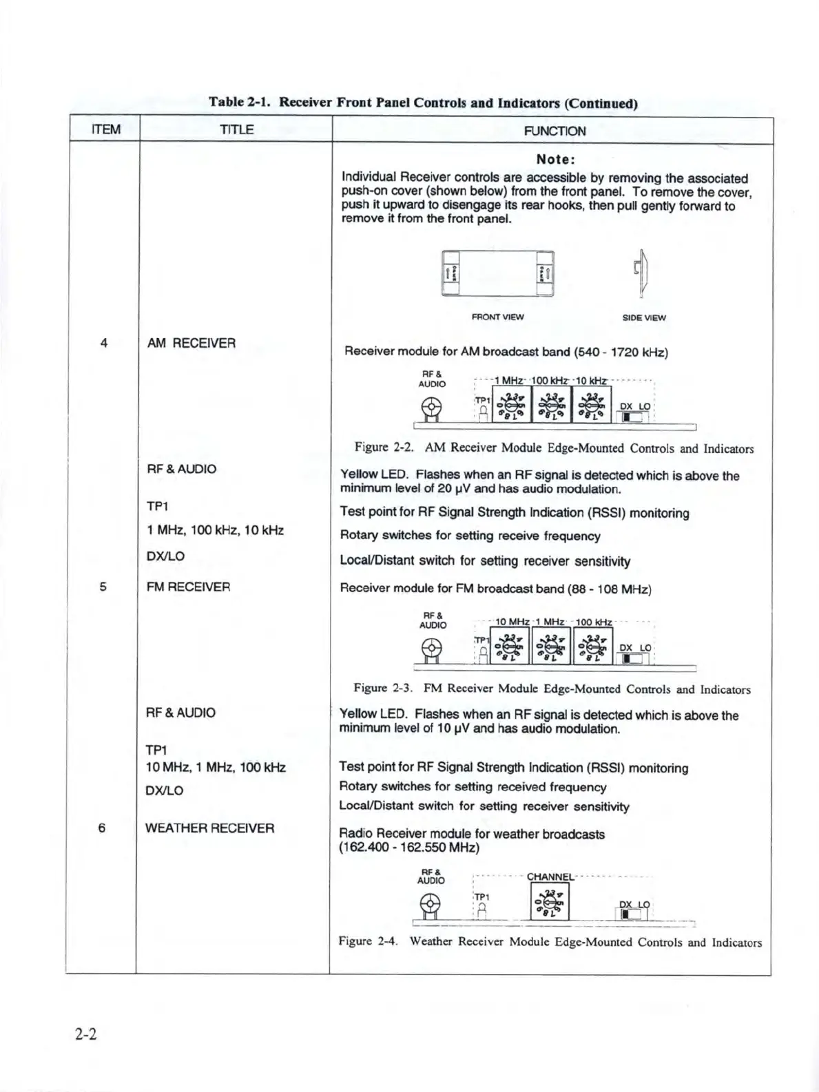
Note:
Individual Receiver controls
are
accessible
by
removing the associated
push-on cover (shown below) from the front panel.
To
remove the cover,
push
it
upward
to
disengage its rear
hooks
, then pull
gently
forward to
remove it from the front panel.
FRONT
VIEW
SIOEVlEW
Receiver module
for
AM
broadcast band (540 •
1720
kHz)
RF&
AUDIO
Figure 2-2.
AM
Receiver Module Edge-Mounted Controls and Indicators
Yellow LED. Flashes when
an
RF
signal
is
detected which
is
above the
minimum level
of
20
µV
and
has
audio modulation.
Test
point
for
RF
Signal Strength Indication (RSSI) monitoring
Rotary switches
for
setting receive frequency
LocaVDistant switch for setting receiver sensitivity
Receiver module for FM broadcast band
(88 • 108
MHz
)
RF&
AUDIO
Figure 2-3. FM Receiver Module Edge-Mounted Controls and Indicators
Yellow LED. Flashes when
an
RF
signal
is
detected which
is
above the
minimum level
of
10
µV
and
has
audio modulation.
Test point for
RF
Signal Strength Indication (RSSI) monitoring
Rotary switches
for
setting received frequency
LocaVD
is
tant switch
for
setting receiver sensitivity
Radio Receiver module
for
weather
broadcasts
(162.400 • 162.550 MHz)
'
RF&
AUDIO
- -
--
CHANNEL
··
·
..
· • • •
---::::._
[i]-=-'
_
Lr
...,_
_
-----""
__
...oB
~~
-=-.=..--
Figure 2-4. Weather Receiver Module Edge-Mounted Controls and Indicators