www.SteamPoweredRadio.Com
Chapter 2 -
Getting
to
Know
Your
EAS
930A
2.1 Unpacking and Inspection
Upon receiving the instrument, inspect
th
e packing box for signs
of
shipping damage. Report any
damage to the transportation company.
Open the shipping box, and verify that it
co
ntains the following items:
• Model EAS 930A Multi-Module Receiver
•
AM
Loop Antenna with Base,
TFf
PIN
2140-7215
• RF Power Splitter 2: 1,
TFf
PIN
1890-0015
• RF Cable Assembly,
Type
F to
Type
F, RG59 (2 each ), TFT PIN 4750-0981
• Power Cord
• Installation and Operation
Gu
id
e,
TFf
PIN
5004-0930A
• Warranty Card
After unpacking, operate the instrument in accordance with the procedures
in
Chapter 3
of
this guide.
If
the instrument is damaged
or
fails to operate properly due to transportation damage, file a claim with
the transportation company
or
,
if
insured separately, with the insurance company.
2.
2 Front Panel Controls and Indicators
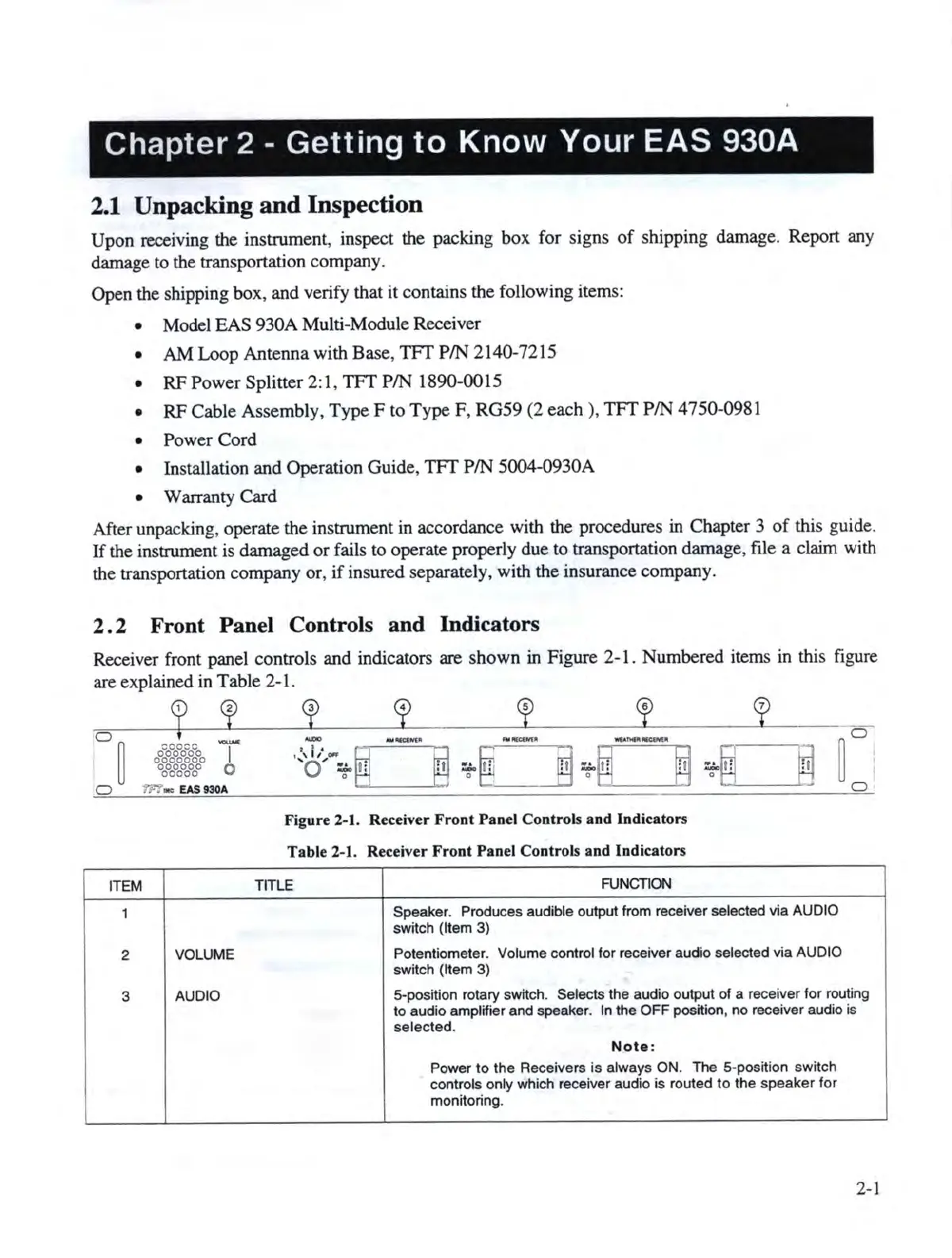
Receiver front panel controls and indicators are sh
ow
n in Figure 2-1 . Numbered items
in
this figure
are explained
in
Table 2-1.
2
01
-
00~0~0~0~0~00
I
oc°
0
o
0
oc°c°
0
D
rn
.,,
EAS930A
ITEM
1
2
VOLUME
3
AUDIO
3
4 s 6
7
..-
...
_,,..
..........
---
r:
<
,l,~
...
~
~
T
@~
T~
~
T~
@
0 T l!
D
Figure 2-1. Receiver Front Panel Controls and Indicators
Table
2-
1. Receiver Front Panel
Co
ntrols and Indicators
TIT
LE
FUNCTION
Speaker. Produces audib
le
output from recei
ve
r selected
via
AUDIO
switch {It
em
3)
Potentiometer. Volume control for receiver audio selected
via
AUDIO
switch (
It
em
3)
5-position rotary switch. Selects the audio output of a receiver for routing
to audio amplifier and speaker. In the
OFF
posit.ion, no receiver audio is
select
ed
.
Note
:
Power
to
the Receivers
is
always ON. The 5-position switch
controls only which receiver audio
is
routed
to
the
speaker
for
monitoring.
2-
1