www.SteamPoweredRadio.Com
5.6 Speaker Amp &
Po
w
er
Supply Board Circuit
De
scription
The
Speaker Amplifier &
Power
Supply
board supplies 5-
and
10-volt
OC
power
for
operation
of
the
Receiver boards. It also contains
an
audio amplifier
to
drive the speaker built into the unit. A front
panel switch allows the audio output
of
a receiver to
be
selected for routing to the audio amplifier and
speaker for monitoring.
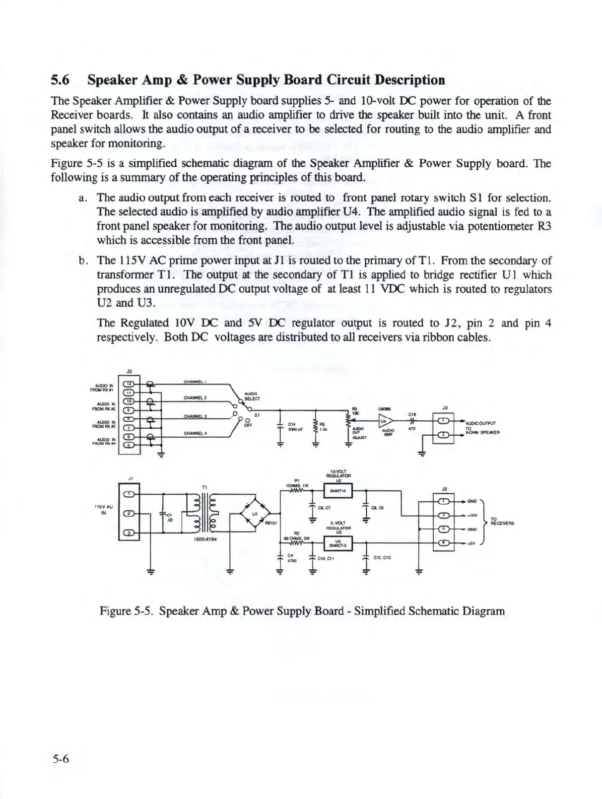
Figure
5-5
is a simplified schematic diagram
of
the Speaker Amplifier &
Power
Supply board. The
following is a summary
of
the
operating principles
of
this board.
5-6
a.
The
audio output from each receiver is routed to front panel rotary switch S 1 for
se
lection.
The
se
lected aud
io
is
amplified
by
audio amplifier U4.
The
amplified audio signal is fed to a
front panel speaker for monitoring. The audio output level is adjustable
via
potentiometer
R3
which
is
accessible from the front panel.
b.
The
115V
AC
prime
power
input
at
J 1 is routed to the primary
of
Tl.
From
the secondary
of
transformer T
l.
The
output
at
the secondary
of
Tl
is applied to bridge rectifier
Ul
which
produces
an
unregulated
DC
output
voltage
of
at l
east
11
VDC which is routed to regulators
U2
and U3.
The
Regulated
IOV
DC
and
5V
OC
regulator output is routed to J2, pin 2 and pin 4
respectively.
Bo
th
DC
vo
ltages are distributed to all receivers via ribbon cables.
n
OWHl.1
OWHl.>
Jt
Tt
11sv
"
c.::
IN
1$0(),.IIM
.,..
..
,_
.,.
'"'
C:11
"'
--i!--+<D+-
..-OUT?UT
.,..
10.\JQ,.,T
-.UTCR
••
ut
ICNd
,
lW
,._
,,,_
<Alf
-
-
l
Cl,C7••\IQ.T
l
.....
A(QI.U
lCIA
..
...
..........
.,.
TO
r--t-C!J-++-
-·
-:-
,12
"'CEM"5
GMO
: }
TO
1--,------,1--~>+--
.••
Figure 5-5.
Speaker
Amp
&
Power
Supply Board - Simplified Schematic Diagram