www.SteamPoweredRadio.Com
Ta
b
le
2-1. Receiver Front Panel Controls and Indicators (Continued)
ITEM
TITLE
FUNCTION
6
RF&AUDIO
Yellow LED. Flashes when
an
RF
signal
is
detected which is above the
(Cont
'd.)
minimum level
of
5
µV
and
has audio modulation.
TP1
Test point for RSSI monitoring
CHANNEL
Rotary switch
for
setting receive channel. See
Table
3-1 for weather
channel frequencies
DX/LO
Local/Distant switch for setting receiver sensitivity
7
(unmarked)
Slot
for additional Receiver Module. Module can
be
any
type
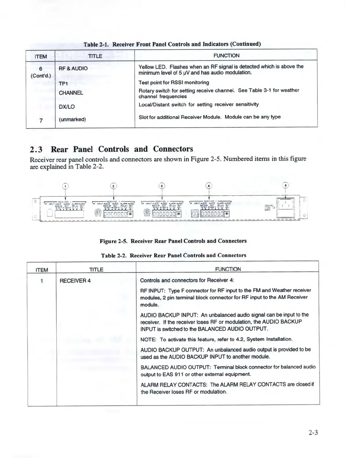
2. 3 Rear Panel Controls and Connectors
Receiver rear panel controls and connectors are shown in Figure 2-5. Numbered items in this figure
are explained in Table 2-2.
17,
........
I
:::
..---.
--c~r-41'.,
---i
~
,.,.,.
...ic.:c
110
'""
APl<I
...aro
•
-::0~
. ;_
th•z
ff,
--1
-,
1
111
1
111
~ )
<v
I
r.:
,
T
'
'
I
~
~t.t~
>
~
,---.
'Ca~
..
.---.
,----
f'((t!\/Clt
I
--,
ff
~·~
.
~Q
-
~
ft!
"'
v,,u,
~t:a
~
~
«
:,,,Vtd.l0
~
"4~~
~
~66n666~
I
l®J
----
-
Figure 2-5. Receiver Rear Panel Controls and
Co
nnectors
Tab
le 2-2. Receiver Rear Panel Controls and
Co
nn
ectors
ITEM
TITLE
FUNCTION
1 RECEIVER4
Controls
and
connectors
for
Receiver
4:
&'
'
I
'
.
j,:
'
,j·
!
.
t£r
~,
111
: .
Ii
01
.,.__.
RF
INPUT: Type F connector
tor
RF input to the
FM
and Weather receiver
modules, 2 pin terminal block connector for
RF
input to the AM Receiver
module.
AUDIO BACKUP IN
PUT
: An unbalanced audio signal can be input to the
receiver. If the receiver loses
RF
or
modulation,
the
AUDIO BACKUP
INPUT is switched to the BALANCED AUDIO OUTPUT.
NOTE:
To
activate this feature, refer to 4.2, System Installation.
AUDIO BACKUP OUTPUT: An unbalanced audio output is provided to
be
used as the AUDIO BACKUP INPUT to another module.
BALANCED AUDIO OUTPUT: Terminal block connector for balanced audio
output to EAS 911
or
other external equipment.
ALARM RELAY CONTACTS: The ALARM RELAY CONTACTS are closed
if
the Receiver loses
RF
or
modulation.
2-3