www.SteamPoweredRadio.Com
Chapter 4 - Installation and Operation
4.
1 Introduction
This chapter describes EAS 930A Multi-Module Receiver system installation procedures
to
be
performed after the unit passes the pre-installation checkout described in Chapter 3.
4 . 2 Model EAS 930A System Installation
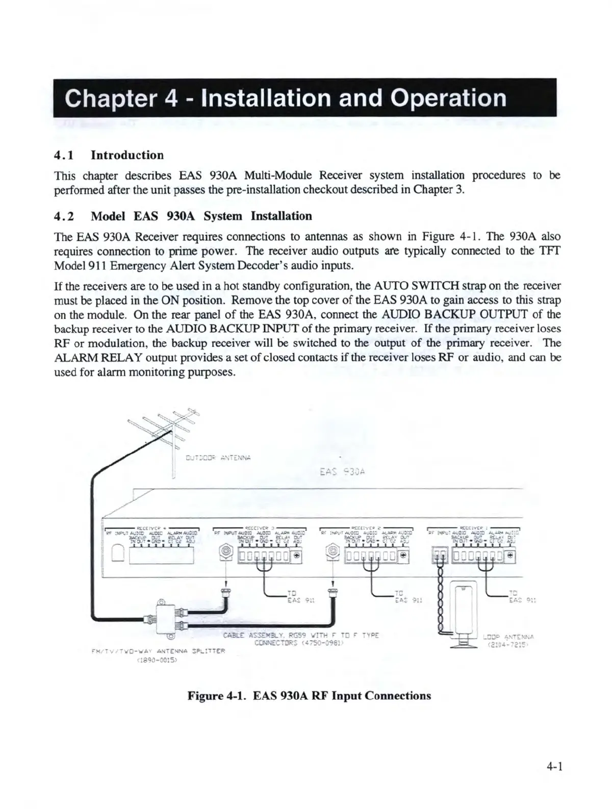
The EAS 930A Receiver requires connections to antennas as shown in Figure 4-1. The 930A also
requires connection to prime power. The receiver audio outputs are typically connected to the
TFf
Model 9
11
Emergency Alert System Decoder
's
audio inputs.
If
the receivers are to be used in a hot standby configuration, the AUTO SWITCH strap on the receiver
must
be
placed in the
ON
position. Remove the top cover
of
the EAS 930A to gain access
to
this strap
on the module. On the rear panel
of
the EAS 930A, connect the AUDIO BACKUP OUTPUT
of
the
backup receiver to the AUDIO BACKUP INPUT
of
the primary receiver.
If
the primary receiver loses
RF
or modulation, the backup receiver will
be
switch
ed
to the output
of
th
e primary receiver. The
ALARM RELAY output provides a set
of
closed
co
ntacts
if
the receiver loses
RF
or
audio, and can
be
used for alarm monitoring purposes.
CA:Bl.E
A$.'.s£
"
3t.
v,
R'GS'!.'
w'!7J-I
•
TC
' •~PE
~EC-rDF::
((750-~8!
:-~
•~
-\i/0-\.IA~
ANi£~'\IA
SF._:-
- ~
<
:sc,a-oo:s,
Figure 4-1. EAS 930A RF Input Connections
4-1