www.SteamPoweredRadio.Com
1 .
3
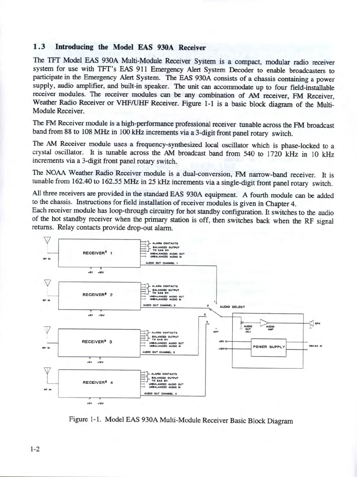
Introducing the Model EAS 930A Receiver
The
TFf
Model
EAS
930A
Multi-Module Receiver System is a compact, modular radio receiver
system for
use
with
TFf
'
s EAS 911 Emergency Alert System Decoder
to
enable broadcasters
to
participate
in
the Emergency Alert System. The EAS 930A consists
of
a chassis containing a power
supply, audio amplifier, and built-in speaker. The unit
can
accommodate
up
to four field-installable
receiver modules. The receiver modules
can
be
any combination
of
AM
receiver,
FM
Receiver,
Weather Radio Receiver
or
VHF/UHF
Receiver. Figure
1-1
is
a basic block diagram
of
the Multi-
Module Receiver.
The
FM Receiver module is a high-performance professional receiver tunable across
the
FM broadcast
band from
88
to
108
MHz
in 100
kHz
increments
via
a 3-digit front panel rotary switch.
The
AM
Receiver module
uses
a frequency-synthesized local
oscillator which is phase-locked to a
crystal oscillator. It
is
tunable across the
AM
broadcast band from
540
to
1720
kHz
in 10
kHz
increments via a 3-digit front panel rotary switch.
The
NOAA
Weather Radio Receiver module is a dual
-co
nversion,
FM
narrow-band receiver. It is
tunable from 162.40
to
162.55
MHz
in
25
kHz
increments
via
a single-digit front panel rotary switch.
All three receivers
are
provided in
the
standard
EAS
930A equipment. A fourth module
can
be
added
to
the chassis. Instructions for field installation
of
receiver modules
is
given in Chapter 4.
Each receiver module has loop-through circuitry for hot standby configuration.
It
switches
to
the audio
of
the hot standby receiver when the primary station
is
off
, then switches back
when
the
RF
signal
returns. Relay contacts provide drop-out alarm.
'v
..,
..
'v
.,
..
71
.,
..
.,,
..
1
-2
RECE
IV
ER
1
1
..
.
.
...
RECEIVER•
2
....
.
...
RECE
I
VER
♦
3
RECEIVERI
4
)-
........
OOlffACTa
}
~°""""
__._,._OUT
---
}-
M..#JIW
co-,TAC"T6
}
rouu~
OVTNT
LNIAli..AHCCO
Al.DO
OUT
_,.....,._IIIICCO
MOIO
tril
}-
...,.,..
CONT
ACTO
}
--
OUffll'f
TO
U8
911
_,.._,._OUT
.............
NCIIOMOON
}----·
}
;~
OVTl'VT
1
.,...,,.u.,cm
AUDIO
OUT
....
4.1,,.ANCIO
A.I.OIO
N
AUDIO
.n.acT
.--.I
,;;-------t-
_:'i
.....
4UOlo
A\.OtO
T"
OUT
,,_
-
...
__
_
•••.....-+----t
POWER
SUPPLY
t-------1-
-••
.,
Figure 1-1. Model
EAS
930A
Multi-Module Receiver Basic Block Diagram