Do you have a question about the TGM MWVT18S / MRVT18AS and is the answer not in the manual?
General instructions to prevent injury and property damage during operation.
Critical safety warnings and precautions for installation and operation of the unit.
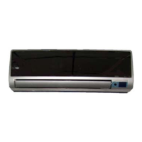
Overview of functions related to the indoor unit of the air conditioner.
Overview of functions related to the outdoor unit of the air conditioner.
Detailed dimensions of the indoor unit, including W, H, and D.
Detailed dimensions of the outdoor unit, including W, H, D, L1, and L2.
Technical specifications for 9K and 12K models across various components.
Technical specifications for 18K and 24K models, covering various components.
Detailed specifications for 12K and 18K models, covering indoor and outdoor units.
Further technical specifications for 18K and 24K models.
Technical specifications for 18K and 24K models, detailing components and performance.
Detailed specifications for 24K models, covering indoor and outdoor unit components.
Detailed specifications for the outdoor unit of 24K models.
Diagram illustrating the refrigerant cycle in cooling-only mode.
Diagram illustrating the refrigerant cycle in heat pump mode.
Defines the operational temperature ranges for cooling, heating, and drying modes.
Schematic showing the electrical connections for the indoor unit.
Schematic for the outdoor unit wiring of specific MRVT models.
Schematic for the outdoor unit wiring of specific MRHVT models.
Schematic for the outdoor unit wiring of MRVT18AS and MRHVT18AS models.
Electrical wiring diagram for the indoor unit of MWVT24S and MWHVT24S models.
Schematic of the outdoor unit wiring for the MRVT24AS model.
Schematic of the outdoor unit wiring for the MRHVT24AS model.
Torque specifications for various fittings during installation.
Guidelines for selecting appropriate power cord specifications for connection.
Table detailing pipe lengths, elevation limits, and additional refrigerant requirements.
Procedure for purging air from the refrigeration piping and indoor unit.
Procedure for pumping down the refrigerant during re-installation.
Procedure for re-purging air from the system during re-installation.
Procedure for balancing refrigerant levels using the 2-way and 3-way valves.
Procedure for evacuating the refrigeration system using a vacuum pump.
Procedure for charging the system with refrigerant.
List of abbreviations for temperature sensors used in the system.
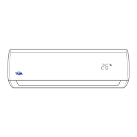
Explanation of icons and indicators on the indoor display board.
Details various protection functions and error codes for the unit.
Description of the Fan-Only operating mode and its fan action.
Explanation of compressor operation rules and anti-freezing function in cooling mode.
Details on rating capacity test function and turbo function in cooling mode.
Features and protection functions specific to the drying mode.
Indoor fan action, auto fan behavior, and compressor frequency rules in heating mode.
Control of outdoor unit current during heating mode.
High temperature protection for the indoor heat exchanger.
Timing diagrams and conditions for defrosting action in different models.
Procedure for the rating capacity test function in heating mode.
Explanation of the turbo function in heating mode.
How the unit selects cooling, heating, or fan-only mode based on temperature difference.
Details on forced cooling and forced auto modes, including touch button operation.
Describes the operation of the 4-way valve in different modes.
Operation of the outdoor fan at different speeds in various modes.
Functionality and settings for the timer feature.
Operation and conditions for the sleep mode.
How the unit resumes operation after a power failure.
Operation of the automatic front panel movement.
Functionality of the ionizer and clean air feature.
Procedure and conditions for the self-clean function.
How the unit controls temperature based on remote controller's sensor.
Function of the optional outdoor chassis heating cable for deicing.
Safety warnings regarding capacitors and high voltage during troubleshooting.
Table listing error codes displayed on the indoor unit and their meanings.
General section for diagnosing and resolving unit issues.
Steps to diagnose and fix EEPROM parameter errors.
Troubleshooting steps for communication protection errors between units.
Steps to diagnose and resolve zero-crossing signal errors.
Troubleshooting indoor fan speed control issues.
Steps to diagnose and fix outdoor temperature sensor errors.
Troubleshooting indoor and evaporator temperature sensor issues.
Diagnosis and solution for IGBT over-strong current protection.
Troubleshooting steps for voltage protection issues.
Diagnosis and solution for compressor top temperature protection.
Troubleshooting steps for inverter compressor drive errors.
Frequently used R-T data for various temperature sensors (T1, T2, T3, T4, Te).
| Model | TGM MWVT18S / MRVT18AS |
|---|---|
| Cooling Capacity | 18000 BTU/h |
| Energy Efficiency Ratio (EER) | 3.21 |
| Coefficient of Performance (COP) | 3.61 |
| Refrigerant | R410A |
| Heating Capacity | 18000 BTU/h |
| Power Supply | 220-240V, 50Hz |