PAGE 6
Fig. 6
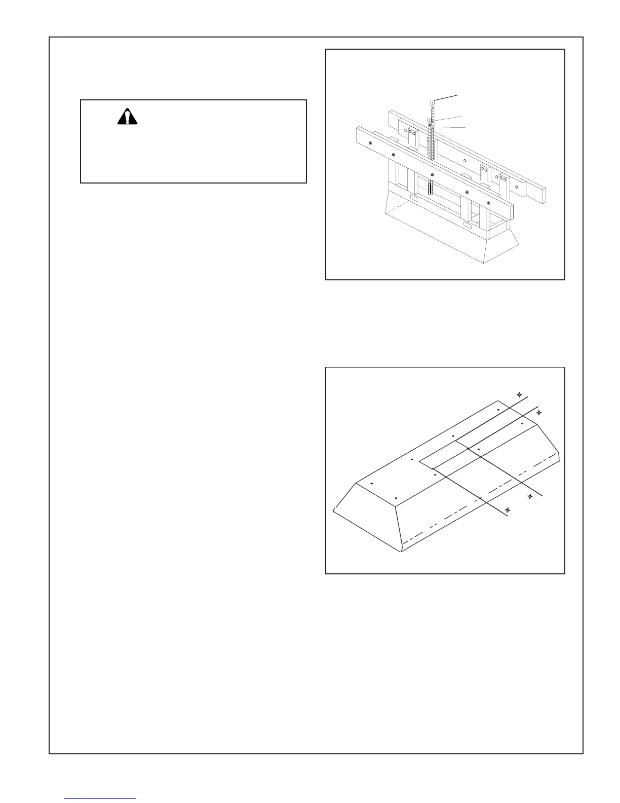
I WIRING TO THE REMOTE VENTILA-
TOR:
a ) Run five wires #12 AWG MIN. (black white, blue, red,
and green) in 1/2" conduit from the remote ventilator
to the J-Box located in the hood assembly. See Fig,
6.
b)
Strip approximately 3/8" at the end of the above wires.
Use the provided wire nuts to connect blue, red, black,
white, and green wires to the corresponding color wires
located inside the J-box. (Note: follow the wiring
diagram.)
I I WIRING TO THE POWER SUPPLY:
a ) Power supply required for this model is 120V., 19
Amps., 60 Hz. Using flex conduit , run three (3) #12
AWG. maximum (black, white, and green) from the
service panel to the J-Box located in the hood. See
Fig. 6.
b)
Strip approximately 3/8" at the end of these three wires.
Use the provided wire nuts to connect the black, white,
and green wires to the corresponding color wires
located inside the J-box. (Note: follow the wiring
diagram.)
c) When using the power supply in a damp location or
outdoors, always install it in a GFCI protected branch
circuit.
STEP 4 -
ELECTRICAL CONNECTION:
SAFETY WARNING:
Turn off power circuit at the service
entrance and lock out panel before
wiring this unit.
Fig.7
Power Supply Wires
Conduit
To Remote Ventilator
23"
8"
STEP 5 -
INSTALL GREASE TROUGHS
AND FILTERS
See Care and Use for instructions.
 Loading...