EasyManua.ls Logo

Thermal Arc 181i Fabricator - User Manual

Thermal Arc 181i Fabricator
106 pages
Print Icon
To Next Page IconTo Next Page
Loading...
Art # A-10455
SMAW
181i
Service Manual
Revision: AC Issue Date: February 28, 2013 Manual No.: 0-5192
Operating Features:
FABRICATOR
3 IN 1 MULTI-PROCESS
WELDING SYSTEMS
3163339

Table of Contents

Questions and Answers

  • H
    holly03Aug 18, 2025
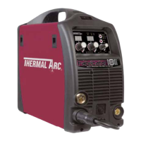
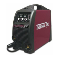
    How to fix inconsistent wire feed on Thermal Arc 181i Fabricator Welding System?
    • L
      louis59Aug 18, 2025
      To fix inconsistent wire feed on your Thermal Arc Welding System, check the following: * Replace a worn or dirty contact tip if necessary. * Replace a worn feed roll. * Reduce excessive brake tension on the wire reel hub. * Clean or replace a worn, kinked, or dirty conduit liner.
  • K
    Kimberly MillerAug 20, 2025
    What to do if there is no gas flow in MIG mode with Thermal Arc 181i Fabricator?
    • I
      ihansonAug 20, 2025
      If no gas flows in MIG mode on your Thermal Arc Welding System, check if: * The gas hose is damaged. If so, replace or repair it. * The gas passage contains impurities. Disconnect the gas hose from the rear of the Power Source and blow out any impurities. * The gas regulator is turned off. Turn the regulator on. * The gas cylinder is empty. Replace the gas cylinder.
  • A
    Anthony KellyAug 22, 2025
    Why welding arc cannot be established in MIG mode on Thermal Arc 181i Fabricator?
    • L
      lparsonsAug 22, 2025
      If your Thermal Arc Welding System's welding arc cannot be established in MIG mode, it might be due to the MIG Gun polarity lead not being connected to a welding output terminal. Connect the MIG Gun polarity lead to either the positive or negative welding output terminal as required. Another possible cause is poor or no work lead contact. Clean the work clamp area and ensure good electrical contact.
  • J
    James LawsonAug 26, 2025
    What to do if Fault Indicator is illuminated on Thermal Arc 181i Fabricator Welding System?
    • J
      John LopezAug 26, 2025
      If the fault indicator is illuminated and the Power Source of your Thermal Arc Welding System won't commence welding, it could be because the duty cycle of the Power Source has been exceeded. Leave the Power Source switched ON and allow it to cool. Note that the fault indicator must be extinguished before you can start welding.
  • L
    Lance Miller MDAug 28, 2025
    Why does welding wire continue to feed after releasing torch trigger on Thermal Arc 181i Fabricator Welding System?
    • W
      whitakereileenAug 28, 2025
      If the welding wire continues to feed after releasing the torch trigger on your Thermal Arc Welding System, it could be because the trigger mode selection switch is in 4T latch mode. Change the trigger mode selection switch from 4T latch mode to 2T normal mode. Alternatively, the torch trigger leads might be shorted; in this case, repair or replace the torch trigger switch/lead.
  • S
    Sharon ShortAug 30, 2025
    What causes Thermal Arc Welding System Power Source not to feed wire in MIG mode?
    • M
      Mark HintonAug 30, 2025
      If the Power Source of your Thermal Arc Welding System won't feed wire in MIG mode, it could be due to the electrode wire being stuck in the conduit liner or contact tip (burn-back jam). Check for a clogged or kinked MIG Gun conduit liner or a worn contact tip. Replace any faulty components. Another possibility is that the MIG GUN/SPOOL GUN switch is switched to SPOOL GUN. Switch the MIG GUN/SPOOL GUN switch to MIG GUN.
  • J
    Jerry GarciaSep 2, 2025
    What to do if Thermal Arc Inverter has no weld output and no display?
    • J
      Joshua HessSep 2, 2025
      If your Thermal Arc Inverter has no weld output and the front panel displays are off, several issues could be the cause. First, ensure the main power switch is set to 'ON'. If it is already on, check the line fuse and replace it if blown. Other potential causes include a faulty main power switch (replace it), a loose connection to the EMC board (tighten connections), a faulty power inverter board (replace it), a faulty control board (replace it), or a faulty display board (replace it).
  • Z
    zlopezSep 4, 2025
    Why Thermal Arc Inverter has no weld output and the display is flickering?
    • C
      Charles EscobarSep 4, 2025
      If your Thermal Arc Inverter shows no weld output and the front panel displays are either off or flickering, it could be due to the internal protection circuit being activated because the mains supply voltage is too high. Check that the mains supply voltage is less than 274VAC. If you're using a generator, its poor voltage regulation might be causing the issue. Connect the power source to a supply voltage less than 274VAC.
  • P
    pmathewsSep 7, 2025
    How to troubleshoot Thermal Arc Inverter with no weld output and a dark display?
    • M
      Mark VangSep 7, 2025
      If your Thermal Arc Inverter isn't welding and the display is dark, start by checking if the main power switch is turned on. If it is, the line fuse might be blown, so replace it. If that doesn't fix it, the main power switch itself could be defective, requiring replacement. Also, check for loose connections to the EMC board and tighten them. If problems persist, the power inverter board, control board, or display board might be faulty and need replacement.
  • M
    mercadolindsaySep 9, 2025
    Why power indicator will not illuminate on Thermal Arc Welding System?
    • M
      Mrs. Donna Newton MDSep 9, 2025
      If your Thermal Arc Welding System's power indicator won't illuminate and a welding arc cannot be established, make sure that the mains supply voltage is within 208/230VAC ±15%. The issue might be that the mains supply voltage has exceeded the voltage limits of the Power Source.

Summary

Safety Instructions and Warnings

Arc Welding Hazards

Details hazards associated with arc welding, including electric shock and burns.

General Safety Information

Covers fire prevention, housekeeping, ventilation, personal protection, and gas cylinder safety.

Principal Safety Standards

Lists key safety standards and codes relevant to welding and cutting operations.

Symbol Chart

Explains symbols used on the equipment and in the manual.

French Safety Precautions

Provides safety guidelines in French for arc welding and related hazards.

General Safety Information (Continued)

Addresses hazards of fire, explosion, flying sparks, engines, batteries, and coolants.

Principal Safety Standards (Continued)

Lists additional safety standards and codes relevant to welding and cutting.

Symbol Chart (Continued)

Presents a chart of symbols used for welding processes and controls.

Declaration of Conformity

Confirms compliance with relevant directives and technical specifications.

Introduction

How to Use This Manual

Explains how to interpret the manual and special annotations like WARNING, CAUTION, and NOTE.

Equipment Identification

Describes how to identify the welding unit by its part number, model, and serial number.

Receipt of Equipment

Provides instructions for checking equipment upon receipt and reporting shipping damage.

Product Description

Details the Fabricator 181i as a multi-process welding system and its capabilities.

Transportation Methods

Offers guidelines for safely moving the welding power source.

User Responsibility

Outlines the user's responsibility for proper installation, operation, and maintenance.

Portable System Package Contents

Lists all components included in the Fabricator 181i Portable System Package.

Safety and Installation

Duty Cycle Explained

Explains the concept of duty cycle for welding power sources with a graphical representation.

Technical Specifications

Provides detailed technical specifications for the Fabricator 181i welder.

Environmental Considerations

Discusses suitable environments for operation, considering humidity, dust, and temperature.

Location Guidelines

Recommends optimal placement for the welder to ensure proper airflow and stability.

Ventilation Requirements

Emphasizes the importance of adequate ventilation to prevent harmful fume accumulation.

Electricity Supply Voltage

Specifies the required input voltage range and electrical connection requirements.

Electromagnetic Compatibility (EMC)

Addresses user responsibility for EMC, area assessment, and methods to reduce emissions.

Volt-Ampere Curves

Illustrates the voltage and amperage output capabilities for different welding processes.

Operation

Power Source Controls and Features

Identifies and explains the function of front and rear panel controls, indicators, and features.

Attaching the MIG Gun

Provides step-by-step instructions for connecting the Tweco Fusion 180A MIG Gun.

Torch Adapter Thumb Screw Replacement

Details the procedure for replacing a thumb screw on the torch adapter.

Installing Wire Spools

Explains how to install both 4" (100mm) and 8" (200mm) diameter wire spools.

Wire Feed Mechanism and Roller Adjustment

Guides on inserting wire into the wire feed mechanism and adjusting feed roller pressure.

Wire Reel Brake Adjustment

Describes how to adjust the friction brake on the wire reel hub.

Gas Regulator Operation

Explains how to operate the gas regulator, adjust flow rate, and shut down the system.

Setup for MIG Welding

Details setup procedures for gas-shielded MIG, gasless FCAW, and Spool Gun MIG welding.

Setup for TIG Welding

Provides instructions for setting up the machine for LIFT TIG welding.

Setup for Stick Welding

Details the procedure for setting up the machine for Stick (SMAW) welding.

Leak Testing the System

Guides on how to perform leak tests on the gas system before operation.

Theory of Operation

Inverter Design

Explains the concept and function of inverter technology in power supplies.

Troubleshooting

Basic Power Source Faults

A table of common faults, their causes, and remedies for the power source.

Pre-Power Checks and Tools

Lists safety checks before applying power and essential tools for troubleshooting.

Case Removal

Step-by-step instructions for safely removing the equipment's outer case.

Clear Cover Sheet Removal and Visual Inspection

Guides on removing the clear cover and performing a visual inspection of components.

Main Inverter Board Checks

Details DC bus voltage measurements and preliminary checks of the main inverter board.

Switch and Rectifier Checks

Explains how to test the main ON/OFF switch and input rectifier.

DC Bus Voltage Measurement

Provides test points and expected voltages for measuring the DC bus voltage.

PCB Connectors and DIP Switch Settings

Lists PCB connectors, DIP switch settings, and their functions for troubleshooting.

Calibration Procedures

Guides on calibrating output voltage, current, and wire feed speed.

Main Circuit Description and Diagram

Describes the main circuit and presents its overall diagram for reference.

Disassembly Procedure

Safety Precautions for Disassembly

Essential safety warnings and precautions before starting disassembly.

Control Board Removal

Step-by-step guide to removing the main control board from the unit.

Front Panel Assembly Removal

Instructions for safely removing the front panel assembly.

Front Panel PCB Removal

Details the removal of the front panel's operator interface circuit board.

Back Panel Removal

Procedure for removing the rear panel of the welding unit.

Power Switch and Cord Removal

Instructions for removing the power switch and input power cord.

Base Panel and Main PCB Disassembly

Guides on removing the base panel and disassembling the main PCB assembly.

Assembly Procedures

Installing Base Board

Steps for installing the main PCB assembly, heatsink, rectifier, and control PCB.

Installing Back Panel

Instructions for installing the gas inlet, ON/OFF switch, wire cord, fan, and rear panel.

Installing Front Panel

Details on reinstalling output terminals, front panel PCB, and connecting cables.

Installing Main Control Panel

Steps for installing the main control panel and clear cover sheet, verifying connections.

Installing Case

Instructions for installing the outer case and ground screw.

Key Spare Parts

Tweco WeldSkill 180 A MIG Gun Parts

Lists part numbers and descriptions for the Tweco WeldSkill 180A MIG Gun.

Tweco Fusion 180 A MIG Gun Parts

Provides part numbers and descriptions for the Tweco Fusion 180A MIG Gun.

Power Source Spare Parts

Lists part numbers and descriptions for various power source components.

Options and Accessories

Accessory List

Catalog of optional accessories and their corresponding part numbers.

Limited Warranty Terms

Warranty Schedule

Details the warranty period for parts and labor for different product categories.

Thermal Arc 181i Fabricator Specifications

General IconGeneral
Input Frequency50/60 Hz
Welding ProcessesMIG, Stick
Wire Feed Speed Range50-500 IPM (1.3-12.7 m/min)
Wire Size Range0.030-0.045 in
Input PhaseSingle Phase

Related product manuals