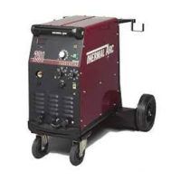
Do you have a question about the Thermal Arc 251 FABRICATOR and is the answer not in the manual?
| Brand | Thermal Arc |
|---|---|
| Model | 251 FABRICATOR |
| Category | Welding System |
| Language | English |
Lists key operational features of the welding machine.
Provides company, copyright, and contact details for the manual.
Details hazards associated with arc welding processes.
Lists key safety standards and publications relevant to welding.
Explains the dangers of electric shock from welding equipment.
Warns about eye/skin damage from arc rays and hearing damage from noise.
Advises on protecting others from arc flash and glare.
Discusses health hazards from welding fumes and gases.
Outlines risks of fire and explosion due to sparks and hot metal.
Warns about injuries from flying sparks and hot metal.
Details risks associated with compressed gas cylinders.
Covers dangers related to engines and their exhaust gases.
Warns about burns from hot coolant and pressure.
States the product may contain chemicals known to cause birth defects or cancer.
Discusses potential health effects of EMFs.
Provides safety precautions specific to arc welding.
Details specific dangers and precautions during arc welding.
Discusses eye/skin protection from arc radiation and hearing protection.
Covers health risks from welding vapors and fumes.
Details risks of fire and explosion from welding sparks and hot metal.
Warns about flying sparks and hot metal causing injury.
Explains risks associated with damaged compressed gas cylinders.
Addresses dangers from engine exhaust gases.
Warns about fire and explosion risks from fuel.
Covers risks associated with moving parts like fans and belts.
Explains how to effectively use the service manual.
Guides on how to identify the welding unit and its parts.
Provides a reference for symbols used on the welding machine.
Offers general details about the welder's specifications and design.
Lists fundamental safety rules for operating the welding machine.
Recommends filter lens shades for welding eye protection.
Explains the concept of rated duty cycle for welding power supplies.
Details the MIG gun and wire drive specifications for the welder.
Lists detailed technical specifications for the Fabricator 251 welder.
Lists items included in the Fabricator 251 package.
Refers to the appendix for optional accessories and equipment.
Describes suitable and unsuitable environments for welder operation.
Provides guidelines for positioning the welding power supply.
Emphasizes the importance of adequate ventilation for welding areas.
Details voltage and fuse requirements for the primary power supply.
Specifies lead sizes for alternative mains supply voltages.
Explains how to change the unit's voltage setting from 230V to 208V.
Provides basic steps for quickly setting up the welding unit.
Details the process of installing shielding gas for GMAW.
Illustrates the steps for installing a gas cylinder with the welder.
Guides on adjusting the gas regulator flow rate for welding.
Explains how to connect the MIG gun and cable to the power source.
Shows how to route the gun cable and connect the trigger.
Details securing the gun cable to the adapter socket.
Guides on installing the wire guides for proper wire feeding.
Explains how to select and install feedrolls for different wire types.
Provides instructions for mounting a wire spool onto the welder.
Details the steps for threading welding wire into the feedhead.
Guides on adjusting the feed roll pressure for optimal wire feeding.
Explains how to adjust the wire spool hub brake tension.
Details how to attach a spool gun to the welding unit.
Explains how to change the welding polarity for different processes.
Provides step-by-step instructions for changing the polarity on the machine.
Identifies and explains the various controls on the welder's front panel.
Describes the function of the power switch and its indicator light.
Explains the digital display for monitoring welding current and voltage.
Provides charts for converting amperage readings to wire speed (IPM) for steel.
Offers a chart for converting amperage to wire speed for aluminum.
Explains the thermal overload protection system and its reset procedure.
Details the function of the wirespeed control knob.
Explains the purpose and connection of positive and negative welding terminals.
Describes how the gun polarity lead sets the welding voltage polarity.
Details the spool gun connection and pin functions for the 10-pin receptacle.
Explains how the weld mode selector sets the welding method.
Describes the 2T mode for continuous welding operations.
Explains the SPOT welding mode and its control settings.
Details the STITCH welding mode and its timer controls.
Explains the 4T latch mode for long weld runs.
Describes the burnback control function for wire feed.
Introduces the TWECO Weldskill 300 AMP gun and its features.
Guides on how to install or remove a wire conduit for the MIG gun.
Illustrates how to trim the conduit for proper installation.
Provides instructions for maintaining the MIG gun.
Offers guidance on basic welding techniques and power supply settings.
Shows recommended distances for contact tips relative to the workpiece.
Lists factors influencing the choice of electrode wire size.
Details how to perform stitch welding operations.
Explains how to perform spot welding operations with the machine.
Provides a chart for selecting shielding gas based on material and thickness.
Offers a guide for selecting welding settings based on material and wire type.
Displays a chart for setting voltage and wire speed based on material thickness.
Outlines routine maintenance and inspection procedures for the welder.
Provides a schedule for performing maintenance tasks on the welding equipment.
Offers basic troubleshooting steps for common issues without disassembly.
Addresses common welding problems, starting with porosity issues.
Lists causes and remedies for inconsistent wire feeding problems.
Details common welding defects like undercut, lack of penetration, and lack of fusion.
Continues troubleshooting for welding issues like arc cracking and cold weld puddles.
Identifies power supply issues and their potential causes and solutions.
Lists initial checks and visual inspections before advanced troubleshooting.
Specifies initial control settings and cable connections for testing.
Outlines tests to verify primary power input and basic operation.
Details tests for logic and control functions in different weld modes.
Continues testing logic and control functions, including spool gun operations.
Describes tests for the spool gun control interface and voltages.
Details how to test the output voltage across various control switch combinations.
Tests the wire feed and arc establishment functions.
Lists problems related to primary power input and indicator status.
Addresses logic and control issues when the gun switch is depressed or released.
Continues troubleshooting logic and control problems, including wire feeder and gas issues.
Troubleshoots specific problems related to the spool gun control (J1).
Diagnoses issues with low output voltage from the welder.
Addresses problems with arc transfer or wire feed and welding.
Provides a diagram and instructions for testing voltages at the input terminal block.
Details how to test the coarse and fine rotary switches for voltage control.
Explains the procedure for testing the continuity of voltage control switches.
Outlines voltage tests for the MIG timer PCB (PCB2).
Guides on testing the diode readings of the rectifier assembly.
Details how to measure the output voltage of the main transformer.
Explains the circuit operation of the main control PCB.
Describes the circuit operation of the MIG timer PCB.
Explains the circuit operation of the digital volt/amp display PCB.
Details the circuit operation of the spool gun PCB.
Instructions on identifying the equipment for ordering parts.
Explains how to navigate and use the parts list section.
Lists external parts available for replacement.
Lists internal replacement parts, including PCBs and switches.
Lists major electrical and mechanical components for replacement.
Lists additional internal replacement parts.
Lists parts for the spool assembly.
Lists replacement parts for the wire feeder mechanism.
Lists specific replacement parts for the wire feeder.
Lists various MIG gun assemblies available as options.
Lists optional accessories like regulators and flow meters.
Lists contact tip sizes and part numbers for welding.
Lists nozzle sizes and part numbers for welding guns.
Lists wire conduit sizes and lengths.
Provides the circuit diagram for the main control PCB.
Shows circuit diagrams for PCB 4 (Digital Meter) and MIG Timer PCB.
Details specific components and connections on the main PCB circuit diagram.
Presents the circuit diagram for the spot timer functionality.
Shows component details and revisions for the spot timer PCB.
Provides the circuit diagram for the spool gun control PCB.
Illustrates feed roll styles and their compatibility with wire types and sizes.
Outlines the terms and conditions of the limited warranty.
Lists warranty periods for different types of welding equipment and accessories.
Provides contact information for Thermadyne offices worldwide.
