EasyManua.ls Logo

Thermal Arc 201 TS - User Manual

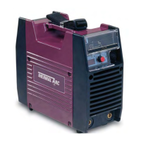
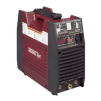
Thermal Arc 201 TS
48 pages
Print Icon
To Next Page IconTo Next Page
Loading...
Art # A-10139
50
60
Hz
32A OUTL ET
STIC K
TIG
230V
110V
TIG/STICK
32A OUTL ET
16A OUTL ET
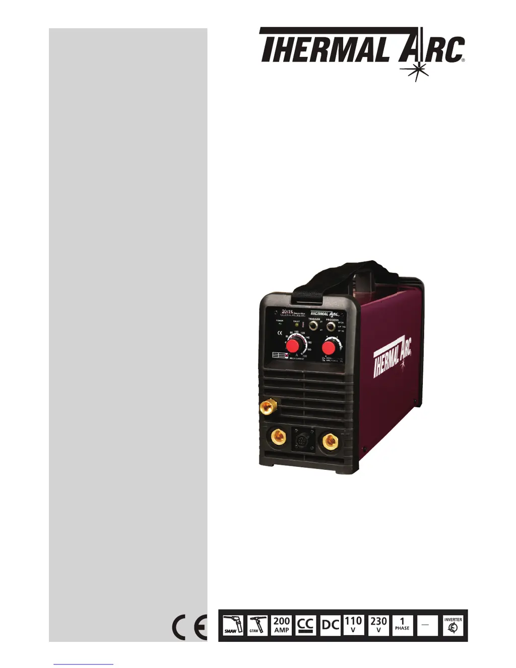
201 TS
Operating Manual
Revision: AB Issue Date: May 20, 2011 Manual No.: 0-5149
Operating Features:
THERMAL ARC
INVERTER ARC WELDER

Other manuals for Thermal Arc 201 TS

Questions and Answers

  • H
    Heather McdowellAug 16, 2025
    What to do if the Over Temp Indicator is on in my Thermal Arc 201 TS Welding System?
    • J
      James StoutAug 17, 2025
      If the duty cycle has been exceeded, reduce weld time and allow the power supply to cool. Also, check the thermostat wire connections. If the connection is properly inserted and the Over Temp Indicator is still on after a short-circuit thermostat, replace the control panel; otherwise, replace the thermostat.
  • J
    jwhiteAug 19, 2025
    Why is the weld output low on my Thermal Arc 201 TS Welding System?
    • A
      ayersheatherAug 19, 2025
      If the input mains are at 230VAC and the output is limited to 125Amps, check the Front panel PCB3 J25 connector and the Main Power PCB1 J16 connector. If they are properly inserted, replace Control PCB2.
  • C
    cristianhahnAug 22, 2025
    Why is the weld output high on my Thermal Arc 201 TS Welding System?
    • S
      Samuel KirbyAug 22, 2025
      If the input is 115V and the output is near 160A, check whether it is shorted between pin1 and pin 3 on the IN JC connector on the main power board. If it is not, replace the control board.
  • C
    christinadavisAug 26, 2025
    What to do if the power indicator is ON but the fan doesn't run on my Thermal Arc Welding System?
    • M
      Meghan GriffithAug 26, 2025
      First, check the fan for any obstructions. Next, verify whether the J12 connector on the main board PCB1 is plugged in properly, ensuring there is +24V±10% on pins 1 and 2 of the J12 connector. If both checks are okay, replace the fan.
  • C
    Charles MillerAug 28, 2025
    What to do if there is no gas flow in Lift Tig / HF Tig Mode on my Thermal Arc Welding System?
    • M
      Megan DelgadoAug 28, 2025
      First, make sure the process switch is functioning properly and set to Lift Tig or HF Tig mode. Next, ensure that pin3 and pin4 of the J12 connector on the main board PCB1 have +24V±10%. If these steps don't resolve the issue, replace the gas solenoid.
  • J
    Jean MossAug 31, 2025
    How to troubleshoot no HF in HF TIG mode on a Thermal Arc Welding System?
    • N
      ngonzalezAug 31, 2025
      Ensure the process switch is functioning properly and set to HF TIG mode. Check the TIG torch switch for continuity. Also, inspect the wire harness on the 8-pin remote connection. If these are okay, measure 15VDC between pins 1 and 3 on (PCB1) J17 when the torch switch is depressed. Verify the HF arc starter wire connection. If the problem persists, replace the main power PCB1.
  • M
    Michelle MccoySep 3, 2025
    What to do if I cannot adjust the weld current on my Thermal Arc 201 TS Welding System?
    • C
      Chelsea HolderSep 3, 2025
      Check the Control panel PCB 3 J26 connector and the Remote control PCB4 J27 connector to ensure they are properly inserted. Also, check the Current Control Potentiometer for an adjustment of 0 to 4.8vdc from Min to Max on Front Panel PCB3, where Pin1=Min, Pin2=Wiper, Pin3=Max. If the adjustment cannot be made correctly, replace Front Panel PCB3.
  • P
    Peter GonzalezSep 6, 2025
    What to do if there is no open circuit voltage on my Thermal Arc Welding System?
    • N
      Nicholas DoyleSep 6, 2025
      First, check the process switch on the front panel to ensure it's functioning correctly. Then, check the Bus voltage on Main Power PCB1; it should read 385VDC. Turn off the power supply, remove Mains Power, and inspect the Input IGBTs and Output Diodes. If incorrect, replace the main power PCB1. If everything above checks out, replace control PCB2.
  • M
    Mr. Patrick AlvarezSep 9, 2025
    Why is the ON/OFF Indicator blinking on my Thermal Arc 201 TS Welding System?
    • L
      Lori WilliamsSep 9, 2025
      Make sure the voltage between pin 1 and pin 2 of the J11 connector on the main power PCB1 is -24VDC±10%, and the voltage between pin 2 and 3 is +24VDC±10%. If the voltage is correct, replace the front panel PCB3. If the voltage is incorrect, disconnect the harness of the J11 connector and re-measure. If still incorrect, replace the Main Power PCB 1.
  • S
    Sean HammondSep 12, 2025
    How to troubleshoot the ON/OFF switch when the power indicator is OFF on a Thermal Arc Welding System?
    • G
      gberrySep 12, 2025
      Check the power supply input. Check the ON/OFF switch continuity. Check the Inrush Resistor. Check the control PCB2 J8 connector and front panel PCB3 J24 connector to ensure they are properly inserted. Replace the front panel PCB3.

Summary

Arc Welding Safety Instructions and Warnings

Arc Welding Hazards and Precautions

Identifies specific hazards like electric shock and necessary precautions.

Welding Safety Precautions and Hazards

Arc Rays, Noise, and Fume Hazards

Details protection from arc rays, noise exposure, and hazardous welding fumes.

Fire, Explosion, and Cylinder Safety

Fire Hazards and Cylinder Safety

Covers welding fire risks, explosion prevention, and compressed gas cylinder safety measures.

Engine Fuel, Battery, and Chemical Safety

Engine Fuel, Battery, and Chemical Warnings

Safety protocols for engine fuel, batteries, and specific chemical alerts (lead, fumes).

Magnetic Fields and Safety Standards

Principal Safety Standards

Lists key industry standards and regulations for welding and cutting safety.

Declaration of Conformity

Introduction to the Manual and Equipment

How to Use This Manual

Explains manual navigation, special annotations, and safety icons.

Equipment Identification

Describes how to locate and record unit identification numbers for reference.

Symbol Chart and Equipment Identification

Symbol Chart

Provides a visual guide to symbols used on the welding machine and in the manual.

Product Description and User Responsibilities

Product Description

Describes the 201TS inverter welder's adjustable current, TIG/STICK modes, and advanced features.

User Responsibility

Defines user obligations for correct installation, operation, maintenance, and preventing modifications.

Understanding Duty Cycle

Technical Specifications

Installation, Operation, and Setup Guide

Environmental Requirements

Specifies suitable environmental conditions and hazards for operating the welder.

Location Guidelines

Provides recommendations for placing the welder to ensure proper operation and safety.

Electrical Input Connections

Electrical Input Connections

Explains how to connect the unit to a single-phase 50/60 Hz AC power supply.

Electromagnetic Compatibility (EMC)

Reducing Electromagnetic Emissions and Setup

Setup for Welding

Provides guidance on connecting the work lead and electrode lead for welding.

Stick (MMA) Welding Setup

Stick (MMA) Mode Sequence of Operation

Lift TIG; HF TIG (GTAW) Setup

TIG System Setup and Leak Testing

Leak Testing the Gas System

Explains how to check the gas system for leaks before operation.

Regulator Shutdown Procedure

Provides instructions for safely shutting down and storing the gas regulator.

Welding Operation Guide

Front Panel Controls and Indicators

Details the function of each button, knob, and indicator on the welding machine's front panel.

Welding Controls and Modes

Trigger Mode Selection (TIG)

Describes the 2T (normal) and 4T (latch) modes for TIG welding control.

Process Selection Switch

Explains how to switch between STICK, LIFT TIG, and HF TIG welding modes.

Welding Current Control Explanation

Stick (MMA) Electrode Polarity

GTAW Electrode Polarity

Selecting Filler Wire

Tungsten Electrode Types

TIG Welding Parameters for Steel

Welding Positions Guide

Joint Preparations for Arc Welding

Basic Arc Welding Technique

Welder Positioning and Comfort

Provides advice on how the welder should position themselves for comfortable and safe operation.

Making Welded Joints

Vertical Welding Techniques

Overhead Welding Techniques

Understanding Welding Distortion

Causes of Welding Distortion

Minimizing Welding Distortion

Service and Maintenance

Maintenance and Inspection Schedule

Outlines routine cleaning, inspection, and maintenance tasks based on usage frequency.

Stick (MMA) Welding Troubleshooting

TIG Welding Troubleshooting

TIG Welding Troubleshooting Continued

Power Source Troubleshooting

Options and Accessories

Replacement Parts List

201 TS System Schematic

Limited Warranty and Schedule

Thermal Arc 201 TS Specifications

General IconGeneral
Input Voltage230V
Input Frequency50/60 Hz
Output Current Range5-200 A
Welding ProcessesTIG, Stick
Input PhaseSingle Phase
Rated Output200 A
TIG StartLift Start

Related product manuals