EasyManua.ls Logo

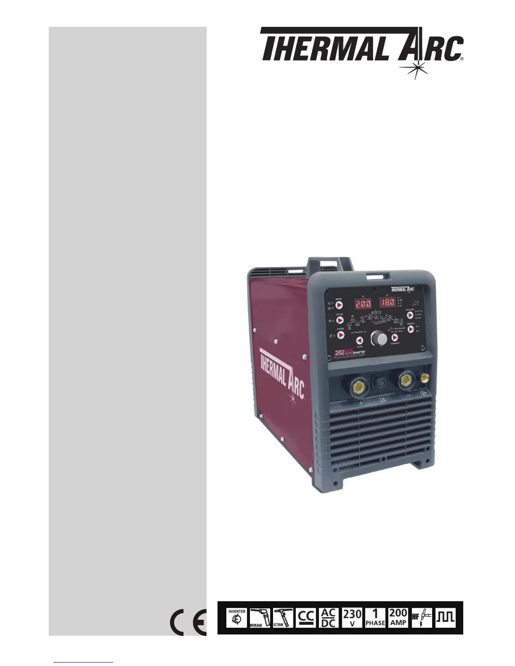
Thermal Arc 202 AC/DC - User Manual

Thermal Arc 202 AC/DC
60 pages
Print Icon
To Next Page IconTo Next Page
Loading...
A-11401
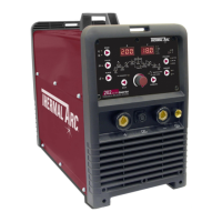
202 AC/DC
Operating Manual
Revision: AB Issue Date: August 6, 2012 Manual No.: 0-5239
Operating Features:
INVERTER
ARC WELDING MACHINE

Questions and Answers

  • R
    Robert AllenJul 30, 2025
    Why does Thermal Arc 202 AC/DC Welding System have gas pockets or voids in weld metal (porosity)?
    • T
      Trevor HawkinsJul 30, 2025
      Porosity in Thermal Arc Welding System can occur due to several reasons: * High levels of sulphur in steel. * Damp electrodes. * Welding current being too high. * Surface impurities such as oil, grease, or paint. * Welding in a windy environment. * Damaged electrode with incomplete flux coating. To resolve this, use an electrode designed for high sulphur steels, dry electrodes before use, reduce welding current, clean the joint before welding, shield the weld area from the wind, and discard damaged electrodes, using only those with a complete flux coating.
  • M
    Michael VaughnAug 3, 2025
    What to do if Thermal Arc Welding System portions of the weld run do not fuse to the surface of the metal or edge of the joint?
    • C
      chavezjessicaAug 4, 2025
      If portions of the weld run do not fuse to the surface, it could be due to using small electrodes on heavy cold plate, welding current being too low, wrong electrode angle, travel speed of electrode being too high, or scale/dirt on the joint surface. To fix this, use larger electrodes and preheat the plate, increase welding current, adjust the electrode angle to direct the arc more into the base metal, reduce travel speed, and clean the surface before welding.
  • A
    amberperezAug 7, 2025
    How to fix a groove formed in the base metal adjacent to the toe of a weld (undercut) with Thermal Arc Welding System?
    • A
      Alexis JacobsAug 8, 2025
      If a groove (undercut) forms in the base metal next to the weld, it may be because the welding current is too high, the welding arc is too long, the electrode angle is incorrect, the joint preparation doesn't allow the correct electrode angle, the electrode is too large, or there's insufficient deposit time at the edge of the weave. Try reducing the welding current and the length of the welding arc. Ensure the electrode is inclined at least 45° to the vertical face. Allow more room in the joint for manipulating the electrode. Use a smaller gauge electrode and pause momentarily at the edge of the weave to allow weld metal buildup.
  • K
    Kenneth SmithAug 12, 2025
    Why does Thermal Arc Welding System welding current vary?
    • A
      Anthony PierceAug 12, 2025
      The welding current in your Thermal Arc Welding System might be varying because the ARC FORCE control knob is set too high, causing the welding current to change excessively with the arc length. Reduce the ARC FORCE control knob setting until the welding current remains reasonably constant, while still preventing the electrode from sticking when you dig it into the workpiece.
  • K
    Katelyn SullivanAug 20, 2025
    Why Thermal Arc 202 AC/DC Welding System crack occurs in weld metal soon after solidification commences?
    • K
      Kyle McbrideAug 21, 2025
      Cracking in the weld metal of your Thermal Arc Welding System shortly after it solidifies may be due to the rigidity of the joint, insufficient throat thickness, or welding current being too high. To address this, redesign the joint to relieve severe stresses, or use crack-resistant electrodes. Travel slightly slower to allow greater build-up in the throat, and decrease the welding current.
  • R
    Richard DeanAug 26, 2025
    How to avoid a gap left by failure of the weld metal to fill the root of the weld with Thermal Arc 202 AC/DC Welding System?
    • A
      Anthony DillonAug 26, 2025
      To prevent gaps due to the weld metal not filling the root when using the Thermal Arc Welding System, increase the welding current, use a smaller diameter electrode and allow a wider gap.
  • T
    thomas42Nov 16, 2025
    What causes non-metallic particles trapped in the weld metal of Thermal Arc 202 AC/DC?
    • B
      Bryce WalkerNov 16, 2025
      Non-metallic particles in the weld metal of your Thermal Arc Welding System can be caused by: * Non-metallic particles trapped in undercut from a previous run. * Joint preparation being too restricted. * Irregular deposits allowing slag to be trapped. * Lack of penetration with slag trapped beneath the weld bead. * Rust or mill scale preventing full fusion. * Using the wrong electrode for the welding position. To resolve this, clean any bad undercut and cover it with a run from a smaller gauge electrode. Ensure adequate penetration and room for cleaning out slag. Chip or grind out any irregularities. Use a smaller electrode with sufficient current for adequate penetration and remove all slag from corners. Clean the joint before welding, and use electrodes designed for the welding positio...

Summary

SAFETY INSTRUCTIONS AND WARNINGS

Arc Welding Hazards

Details potential dangers associated with arc welding, including electric shock.

Principal Safety Standards

Lists key industry standards relevant to safe welding practices.

Symbol Chart

Explains symbols used on the equipment for user understanding.

Declaration Of Conformity

States compliance with relevant European directives and national legislation.

INTRODUCTION

How To Use This Manual

Guidance on effectively using the operating manual for safe and efficient operation.

Equipment Identification

Information on locating and identifying the welding unit's specifications.

Receipt of Equipment

Instructions for checking equipment upon delivery for completeness and shipping damage.

Description

Overview of the Thermal Arc 202 AC/DC's capabilities and features.

User Responsibility

Defines the user's role in ensuring correct installation, operation, and maintenance.

Transporting Methods

Safe procedures for moving the welding power source.

Packaged Items

Lists the components included with the 202 AC/DC inverter system.

Specifications

Technical data and ratings for the welding power source.

Duty Cycle

Explanation of the machine's performance limits based on welding current and time.

Optional Accessories

Information on available accessories to enhance the welding system.

INSTALLATION, OPERATION AND SETUP

Environment

Guidelines for selecting a suitable operating environment, considering electrical hazards.

Location

Criteria for choosing the proper placement of the welder for optimal performance and safety.

Ventilation

Highlights the importance of adequate ventilation for welding fume removal.

Mains Supply Voltage Requirements

Specifies the required mains supply voltage and frequency for correct operation.

High Frequency Introduction

Information on the proper installation of high frequency welding initiation.

High Frequency Interference

Guidance on managing and preventing interference from high frequency welding.

Electromagnetic Compatibility

Considerations for electromagnetic compatibility in various operating environments.

202 AC;DC Power Source Controls, Indicators and Features

Detailed explanation of the front and rear panel controls, indicators, and features.

202 AC;DC - STICK Programming Mode

Instructions for setting up and operating the machine in STICK (MMA) welding mode.

202 AC;DC - LIFT TIG and HF TIG Programming Mode

Instructions for setting up and operating the machine in LIFT TIG and HF TIG modes.

Short Circuit Protection While Welding

Details circuitry designed to protect TIG tungsten electrodes during short circuits.

Victor Regulator

Guidance on the installation and use of the Victor pressure regulator.

Setup for TIG (GTAW) Welding

Step-by-step instructions for setting up the machine for TIG welding.

Setup for STICK (MMA) Welding

Step-by-step instructions for setting up the machine for STICK welding.

BASIC WELDING GUIDE

Stick (MMA) Basic Welding Technique

Fundamental techniques for performing Stick (MMA) welding.

Stick (MMA) Welding Troubleshooting

Common problems and solutions encountered during Stick (MMA) welding.

TIG (GTAW) Basic Welding Technique

Fundamental techniques for performing TIG (GTAW) welding.

TIG (GTAW) Welding Problems

Common problems and solutions encountered during TIG (GTAW) welding.

POWER SOURCE PROBLEMS AND ROUTINE SERVICE REQUIREMENTS

Basic Troubleshooting

Initial steps for diagnosing and resolving common welding power source issues.

Power Source Problems

Identifies specific faults, their causes, and remedies for the welding power source.

Routine Service and Calibration Requirements

Guidelines for regular maintenance, testing, and calibration of the power source.

Cleaning the Welding Power Source

Procedures for safely cleaning the internal and external components of the welder.

KEY SPARE PARTS

Power Source

Diagram and list of key spare parts for the welding power source unit.

APPENDIX: CIRCUIT DIAGRAM

LIMITED WARRANTY & WARRANTY SCHEDULE

Thermal Arc 202 AC/DC Specifications

General IconGeneral
BrandThermal Arc
Model202 AC/DC
CategoryWelding System
LanguageEnglish

Related product manuals