Do you have a question about the Thermal Arc 300GTSW Pro-Wave and is the answer not in the manual?
Details potential dangers and precautions for arc welding operations.
Lists applicable industry standards and safety regulations for welding.
States compliance with relevant European Directives and National legislation.
Outlines the terms and conditions of the product warranty.
Guidance on navigating and utilizing the service manual effectively.
Information on locating unit identification numbers for reference.
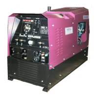
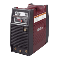
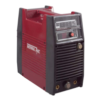
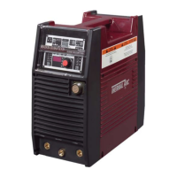
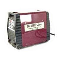
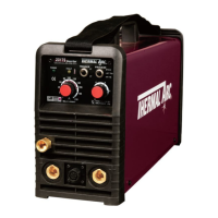
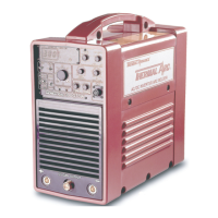
Overview of the Thermal Arc 300GTSW welding power source.
Detailed technical specifications including output, input, and dimensions.
Explanation of duty cycle and its impact on operation and performance.
Instructions for proper electrical hookup and input voltage requirements.
Description of front panel controls for operating the welding unit.
Identification and function of controls located on the rear panel.
Guidelines for regular cleaning and inspection of the unit.
Initial steps to diagnose and resolve common operational problems.
Detailed troubleshooting guide for various unit symptoms and faults.
Procedure for isolating defective subsystems within the power supply.
Steps for safely accessing the internal components of the unit.
Procedure to verify input and internal voltages for diagnostics.
Detailed instructions for removing and replacing the main circuit board.
Steps to test the function of the IGBT inverter assemblies.
Procedure for accessing and replacing output diodes.
Information required for identifying the unit when ordering parts.
Guidance on navigating and understanding the parts list.
Comprehensive list of all replaceable parts with catalog numbers.
Illustrations of key components and their locations within the unit.
| Input Voltage | 208/230/460 V |
|---|---|
| Input Frequency | 50/60 Hz |
| Output Current Range | 5-300 A |
| Output Voltage Range | 10-32 V |
| Duty Cycle | 60% at 300 A |
| Welding Processes | GTAW (TIG), SMAW (Stick) |
| Rated Output | 300 A at 32 VDC |
| Input Phase | Single/Three Phase |