APPENDIX A-12 Manual 0-2962
APPENDIX 5: CUTMASTER 100 & 101 SYSTEM DATA
(HAND AND MACHINE TORCH)
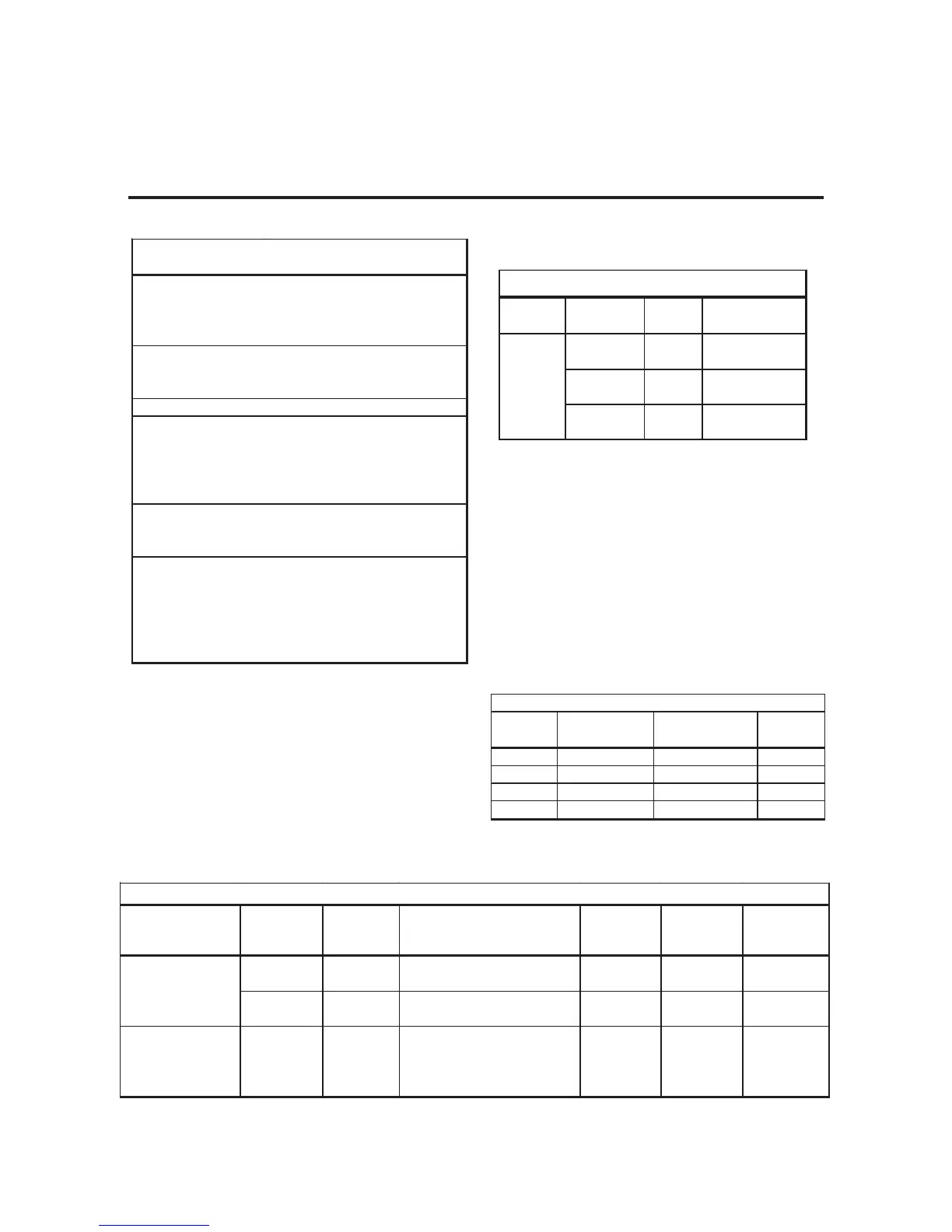
Cut Quality on Various Materials and Thicknesses
The following table defines the cut quality on various
materials and thicknesses:
Cut Quality on Various Materials
Material Type of Type of Cut
ThicknessMaterialGas Characteristics
Gage
to
Air
Air
Air
Good - Excellent
Good
Good
Carbon Steel
Stainless
Aluminum
1 inch
( 25.4 mm )
Description of Cut Characteristics:
Excellent - Minimum bevel (0 - 4°), minimum kerf (2 x tip
orifice diameter), little or no dross, smooth
cut surface.
Good - Slight bevel (0 - 10°), slightly wider kerf (2-1/2 x
tip orifice diameter), some dross (easily removed),
medium - smooth cut surface, slight top edge
rounding.
Cutting Range
Material Most Metals
Up to 1 inch / 25.4 mm
Speed 10 ipm / 0.25 mpm
Pierce Rating
Material Carbon Steel
Thickness3/8 inch / 9.5 mm
Transfer Distance
3/8 inch / 9.5 mm
Gouging
Width1/4 inch - 6.3 mm
Depth3/16 inch - 4.8 mm
Number PassesSingle
Speed 20 ipm / 0.5 mpm
Bevel Cut Ca pability
Degrees 0° to 45°
Material Thickness1/2 inch - 13 mm
Gas Requirement
Type GasAir
Operating Pressure 70 psi / 4.8 bar
Max Input Pressure 125 psi / 8.6 bar
Cutting & Gouging
Total Flow
490 scfh / 231 lpm
Torch Specifications For
CutMaster 100 & CutMaster 101 Power Supplies
Output
Range
Dept
idth
Tip A 40 Amps Max. ShallowNarrow
Tip B 40-100 Amps Deep Narrow
Tip C40-100 Amps Moderate Moderate
Tip D40-100 Amps Shallo
ide
Gouging Profiles
ApplicationElectrode
Starter
Cartridge
Tip
Shield
Cup Body
Shield Cap
or Deflector
Shield Cup
9-8215 9-8213 9-8211 (80A)NoneNone9-8218
9-8215 9-8213 9-8211 (80A)9-8237
9-8239 or
9-8243
None
Gouging9-82159-8213
Tip A: 9-8225 (40A Max)
Tip B: 9-8226 (40-100A)
Tip C: 9-8227 (40-100A)
Tip D: 9-8228 (40-100A)
9-8237 9-8241 None
SL100 Machine Torch Consumables for 80-Amp Power Supply
Standoff Cutting

 Loading...