Do you have a question about the Thermalright Le GRAND MACHO and is the answer not in the manual?
Diagram showing all components and their placement for specific Intel sockets.
Diagram illustrating component layout for Intel LGA 2011/2011-3 sockets.
Diagram showing component arrangement for AMD platforms.
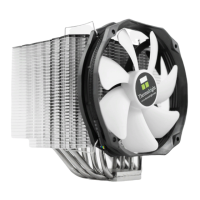
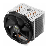
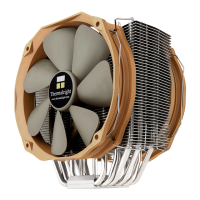
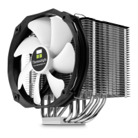
The primary cooling element of the Le GRAND MACHO.
Part used for securing the heatsink to the motherboard.
Structural plate often used for support and mounting.
Plate that connects the heatsink assembly to the mounting hardware.
Fastener used to secure components during installation.
Specific screw pillars for Intel LGA2011 socket mounting.
Screw with M3 thread and 10mm length for assembly.
Screw with M3 thread and 6mm length for assembly.
Small washer for Intel mounting systems.
Larger washer for AMD mounting systems.
Pads designed to reduce vibration and noise.
A cap for the backplate, possibly for specific socket types.
Clips used to attach the fan to the heatsink.
Likely refers to thermal paste or a cooling accessory.
Tool included for installation.
The specific model of the fan included with the cooler.
Film used in the mounting process, possibly for insulation or protection.
Attaching screw pillars and backplate for Intel platforms.
Installing the backplate cap for LGA 775 sockets.
Placing the motherboard and securing it with screw nuts.
Attaching the anchoring mount to the screw nuts.
Applying thermal paste to the CPU and heatsink base.
Positioning the heatsink and mounting plate, securing with screws.
Using the screwdriver through the heatsink for easier screw access.
Attaching the fan to the heatsink using fan clips.
Final step of connecting the fan to the motherboard.
Installing LGA2011 Type B screw pillars onto the motherboard frame.
Securing the anchoring mount with M3L6 screws.
Applying thermal paste to the heatsink and CPU surface.
Attaching anti-vibration pads and the mounting plate.
Using the screwdriver through the heatsink for easier screw access.
Attaching the fan to the heatsink using fan clips.
Final step of connecting the fan to the motherboard.
Attaching screw pillars and backplate for AMD platforms.
Installing the backplate cap for AMD sockets.
Placing the motherboard and securing it with screw nuts.
Attaching the anchoring mount to the screw nuts.
Applying thermal paste to the heatsink and CPU surface.
Attaching anti-vibration pads and the mounting plate.
Using the screwdriver through the heatsink for easier screw access.
Attaching the fan to the heatsink using fan clips.
Final step of connecting the fan to the motherboard.
Details on heatsink dimensions, weight, heatpipes, and base material.
Details on fan dimensions, speed, noise, airflow, and connector type.
| Brand | Thermalright |
|---|---|
| Model | Le GRAND MACHO |
| Category | Computer Hardware |
| Language | English |