Description and use
Instalace
Warning:
Only qualified person can do installation and connection of thermostat to integrated
circuit in accordance with notice nr.50/1978 mim.§ 6.
Installation only without voltage!
1. Put thermostat on pipe with whole contact area. For better transmission is good
to apply attached heat transfer paste on contact area.
2. Fasten thermostat with attached spring.
3. Remove regulatory button and loos fixation screw 2 , for loose the case 3 .
4. Thread the connected conductor through power supply bushing 4 , and tighten
attached conductor to thermostat clamp a , b , c , according to requested
function. Connect ground cable to ground clamp 4 . Temperature differnece can
be adjusted with difference setting e .
5. Put on case 3 , tighten fixation screw 2 , put on regulatory button 1 .
Pay attention to straight position of thermostat shaft while putting on
regulatory button.
1
Installation
InstalaceStoring conditions
Storing can be done in closed and aired rooms within temperature range
15–60 °C. Storing and trasfer must not cause a mechanical damage of the
device. Thermostats must be treated with care, with no major shocks or
vibrations.
InstalaceDisposal
Disposal should be performed as follows: Hand into a recycling collection
point.
InstalaceWarranty
Provided, that the product has been placed and used according to the
instruction manual, the manufacturer provides with warranty in compliance
with a valid code, unless agreed otherwise.
The manufacturer will reject warranty repair, in case the product has been
damaged:
- during tranport and storage of the purchaser, or his customers,
- during installation or disassembly of device of the purchaser or his
customer.
InstalaceWarranty and post-warranty repairs
Warranty and post-warranty repairs are provided by the manufacturer. Warranty
claim of a faulty thermostat should be done at the seller. The warranty claim will be
accepted in case, that following requirements are met:
- submitted warranty list of the given thermostat,
- paid invoice of the thermostat,
- the conditions and requirements of operating manual were met.
3
1
U
L
N
PE
+°C
° °
°
2
Instalace
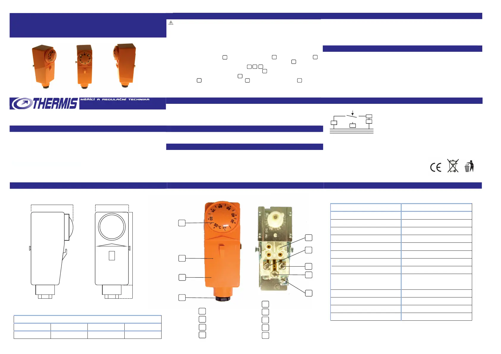
Wiring diagram
Design
Description
ypeT THP-90
-90°CTemperature range 20
8±3KTemperature difference adjustable 1-
IP 0IP protection 2
<1K/minRate of temperature change
85°CTmax surrounding
15-60°CStoring temperature
Output NO/NC
IInsulation class
=16( )A/250V~Contact load 1-2 2,5
= V~1-3 2,5A/250
Installation common environment
M20x1,5Output pipe
Mounting on pipe
Design freely accessibly or covered regulation
1 -2 switch-off at reaching adjusted temperature
1 -3 switch-on at reaching adjusted temperature
Technical parameters
info@thermis.cz, www.thermis.cz
54 38 99 20
Dimensions in mm
a b c d
1 regulatory button
3
2 fixation screw
1
2
3 case
4 power supply bushing
4
a
c
d
a clamp 2
b clamp 3
c clamp 1
d ground clamp
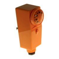
Cased contact thermostat THP 90 is used in applications, where is emphasis on
design and easy control, or where it is suitable to prevent straight touch with
contacts. Widely used for switching of boiler or solar system circulation pump. Main
advantages of these thermostats are easy control, mounting and reliability.
Thermostats THP 90 feature change-over contact for connection and disconnection
of electric circuit. Thermostat case guarantees protection IP 20.
INSTRUCTION MANUAL
cased contact thermostat THP 90
Certificate of conformity:
For evaluation of conformity was used protocol nr.6450-004/2009
Harmonized norms: ČSN EN 61010-1:2003, ČSN EN 60695-2-11:2001
a
b
c
d
e difference setting
b
e
 Loading...