Disassembly and Reassembly
(Bev.
7, 12l01)
Repair
NOTE: Ualve plates
musr scal co,npletelr o. thc comprcs-
sor win lose capacitJ.
L
lnspecl the cage. ring valve. valve spring.
and relain€r
tbr
wear
or damage.
2. Valve plales
may be lested by
pourinc
clean fluid
(Stodard
solven, inlo thc deprcssion
ofthe
valve plale.
The solvcnt should not leak
throuSh. lf the valve
plnte
assembly is wom,
damaged or leaks. replnce it wirh a
new assembly. Rcmove all
lraces of
solvenl
betbre
inshlling the valv€ plate
assembly.
1.
I
Solvent
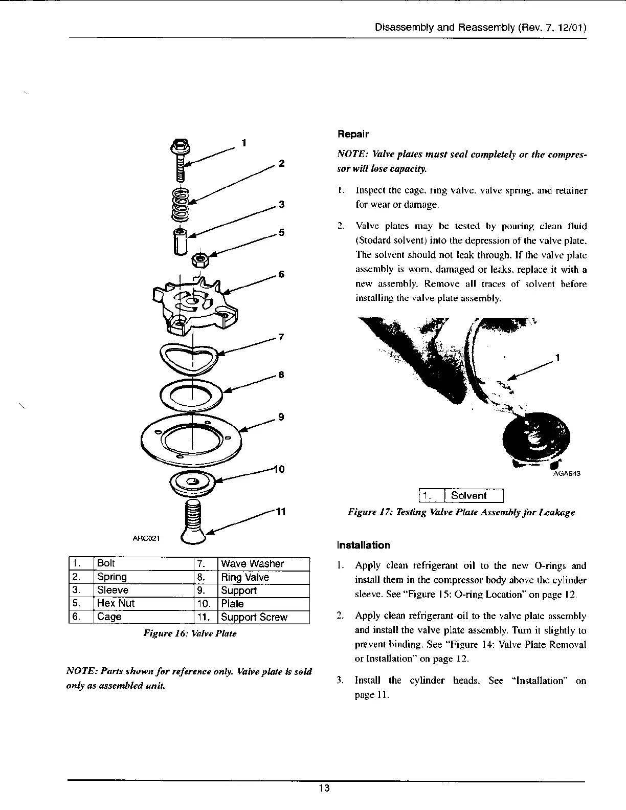
1 Bolt
7.
2. Spring
8. Rino Valve
3. Sleeve
9. Support
5.
Hex Nut 10.
Plate
6. Cage
']l
Supporl Screw
Figure
16: Uabc Plate
Figurc
17:
Testing
Ualve Platc Assenblf
fo.
Iaohage
Inatallalion
l. Apply clean refrigemot
oil to the new O-rings and
inst,tll them in
the compressor body above rhe
cylinder
slccve.
See
"Figure
15: O-ring Location" on page
12.
2. Apply clenn rcftgeranl
oil to the valve
plare
assembly
and install
the
valve plate
assembly. Tum it sliShlly
10
prevent binding.
See
'Figure
14: Valve Plat€
Rernoval
or Installarion" on
page
12.
3. Install the cylinder heads.
See
"lnstallation
on
page
I l.
NOTE: Pans
shown
lot
nfeftnce only, Valve plate
is solt
only as assenbled unit.