Unloader Head
Operation
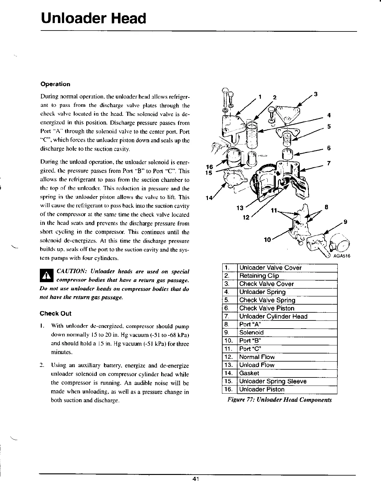
During normalopendoD.
the unlonder hcrd
aUows
refriger-
ant to
pass
from
the discharge valvc pla(es
through the
check
valve
located in
the head. Thc solenoid valve
is de-
energizcd in
this
position.
Discharge pressure passes
fronr
Porl A
through the solenoid valle
lo rhe cenrer
porl.
Pon
''C",
$hich forces
the unlonder pisron
down.rnd seals up
rhe
discharge hole ro thc suction
cavily.
Dunng
the unload opcration,
the unloadcr solcnoid
is ener-
gized.
thc prcssure passes
frcm Pon
B" 10 Pod
'C
. This
rllows the rcfrigeran(
to
pass
from
rhe suclion chamber to
thc bp of
thc unloadc': This rcduction
in
prcssu'.c
and
the
sp.iDg in
thc unloder pisloD
allows {hc valvc ro lift.
This
w;llcausc
lhe rclrigennt to pNs
back inro lhe sucrioncavily
ol lhe comprcssor rr
the
samc
time rhc
chccl,
valve
lo€aled
in
(he
head scars
and
prevenrs
rhc
discharge
pressure
fn)rn
shon cycling in
the compressor This
conlinues unril rhc
solcnoid
dc-cncrgizcs. Al
this
(ime
the discharg€ prcssure
builds up. se ls offthc pon
to lhe suction
cavily and rhe sys-
tcnr
punrps
wilh four
cylinders.
CAUTION:
Unloader heah arc
used on spcci&l
conprcssor
bodies that haw
s rcturn
gas passage.
Do not use
unloadcr heads on
conpressor bodics that
do
not havc th. .eturn gas passaAe.
Check Out
l.
with
unloadcr
dc-energized. conpressor
should
punp
down nomally
15 to 20 in. Hg vacuum
(-51
to
-68
kPa)
and should hold a 15 in.
Hg
vacuum
Csl
kPa)
for three
2. Using
an auxiliary ba[ery,
energize and de-energize
unloader
solenoid on compressor
cylinder hcad white
the compressor is
running. An audible
noise
will
b€
made when
unloading. as well
as a
pressure
change in
borh suction
and discharge.
Unload6r Valve
Cover
2. Retainino Clip
3. Check Valve
Cover
Unloader Sprinq
5.
Check
Valve
Spring
Check Valve Piston
7.
Unloader Cylinder Head
8.
L Solenoid
10. Porl
'8"
11. Port
"C'
Normal Flow
Unload
Flow
14.
Gasket
Unloader Spring
Sl6ev€
Unloader Piston
Figurc 77:
Unloader Head Components
41