J
Jeffrey NorrisAug 19, 2025
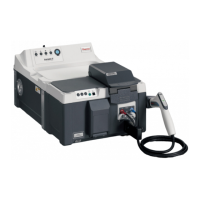
What to do if Thermo Scientific SOLA II display 'Sample Flow' alarm?
- CCurtis HernandezAug 20, 2025
If the Thermo Scientific Measuring Instruments display the 'Sample Flow' alarm, it means the sample supply is inadequate, valves are closed or misaligned, or the filtration system is plugged. Check the process conditions and sample supply availability, ensure all valves are properly aligned, and clean or replace the filters. Also, adjust the bypass flow rate if it is set too high.