- 2 -
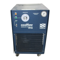
CFT Series Quick Reference Operating Procedures
When the unit is shut off, wait approximately five
minutes before restarting. This allows time for the
refrigeration pressures to equalize. If the pressures
are not allowed to equalize, the compressor will
short-cycle and no cooling will occur.
Temperature Adjustment
To display the temperature setpoint, press the
NEXT ENTER button on the controller. To adjust
the temperature setpoint, press the YES or NO key
until the desired temperature setpoint is indicated.
Once the setpoint is adjusted, press NEXT EN-
TER. The display will now indicate the temperature
of the fluid in the reservoir.
Periodic Maintenance
Periodically inspect the reservoir fluid. If cleaning is
necessary, flush the reservoir with a cleaning fluid
compatible with the circulating system and the
cooling fluid.
The cooling fluid should be replaced periodically.
When operating at low temperatures, the concen-
tration of water in the cooling fluid will increase
over time, leading to a loss of cooling capacity.
Before changing the cooling fluid, raise the unit's
operating temperature to de-ice the cooling coils.
Periodic vacuuming of the condenser fins is
necessary. The frequency of cleaning depends on
the operating environment. We recommend a
visual inspection of the condenser be made
monthly after initial installation. After several
months, the cleaning frequency will be established.
Units with PD pumps have a strainer. If debris is in
the system, the strainer will prevent the material
from being drawn into the pump and damaging the
pump vanes.
After initial installation, the strainer may become
clogged. Clean the strainer after the first week of
installation. After this first cleaning, we recommend
a monthly visual inspection. After several months,
the cleaning frequency will be established. Before
cleaning, disconnect the power cord from the
power source and drain the reservoir.
Installation
The unit has an air-cooled refrigeration system. Air
is drawn in the front of the unit and discharged
through rear and side. Position the unit so the
intake and discharge are not impeded. Inadequate
ventilation will cause a reduction in cooling capac-
ity and, in extreme cases, compressor failure.
Excessively dusty areas should be avoided and a
periodic cleaning schedule should be instituted.
For proper operation, the unit needs to pull sub-
stantial amounts of air through a condenser. A
build up of dust or debris on the fins of the con-
denser will lead to a loss of cooling capacity.
The unit will retain its full rated capacity in ambient
temperatures up to approximately +24°C.
Make sure the voltage of the power source meets
the specified voltage, ±10%.
The plumbing connections are located on the rear
of the unit and are labelled either SUPPLY and
RETURN or OUTLET and INLET. These connec-
tions are ½ inch FPT, ¾ inch FPT for CFT-150s
with CP-55 pumps and CFT-300s. Remove the
plastic protective plugs from both plumbing con-
nections. Connect the OUTLET/SUPPLY fitting to
the inlet of the instrument being cooled. Connect
the INLET/RETURN fitting to the outlet of the
instrument being cooled.
To fill the reservoir, remove the reservoir access
panel by unscrewing the thumbscrews. Locate the
reservoir plug (square nut). Remove the plug and
fill the reservoir with clean cooling fluid.
We recommend using distilled/deionized water with
a 0.05 to 0.1 megohm-cm reading.
If you do not have access to distilled/deionized
water we recommend using filtered tap water.
Operation
Before starting the unit, double-check all electrical
and plumbing connections. Make sure the circulat-
ing system has been filled with cooling fluid.
To start the unit, place the Power Switch to the on
position. The Power Switch illuminates (except for
the CFT-150) to indicate the system is operating.
To turn the unit off, place the Power Switch to the
off position.
The Cool LED indicates the status of the refrigera-
tion system. It illuminates to indicate the refrigera-
tion system is removing heat from the cooling fluid.
As the operating temperature approaches the
setpoint, the LED will flash.