4N
3269
page
3/17
I.
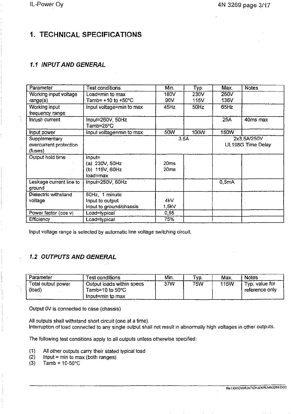
TECHNICAL SPECIFICATIONS
1.1
INPUT AND GENERAL
Parameter
Working input voltage
Working input
frequency range
Inrush current
lnput power
Supplementary
overcurrent protection
Test conditions
I
Min.
TYP.
I
Max.
1
Notes
Tamb= +I0 to +50°C
Input voltage=min to max
Load=min to max
1
180V
1
230V
I
260V
I
lnput=260V, 50Hz
Tamb=2!j°C
Input voltage=min to max
lnput voltage range is selected by automatic line voltage switching circuit.
1.2
OUTPUTS AND GENERAL
90V
45Hz
(fuses)
Output hold time
Leakage current line to
ground
Dielectric withstand
voltage
Power factor (cos v)
Efficiency
50W
1
15V
50Hz
Input=
(a) 230V, 50Hz
(b) 1 15V, 60Hz
load=max
lnput=250V, 60Hz
50Hz, 1 minute
Input to output
Input to groundlchassis
Load=typical
Load=typical
Output OV is connected to case (chassis).
136V
65Hz
1 OOW
Parameter
Total output power
(load)
I
Input=min
to
max
All outputs shall withstand short circuit (one at a time).
Interruption
of
load connected to any single output shall not result in abnormally high voltages in other outputs.
3,5A
20ms
20ms
4kV
1,5kV
0,55
75%
Min.
37W
Test conditions
Output loads within specs
Tamb=lO to 50°C
The following test conditions apply to all outputs unless otherwise specified:
2x3,5A/2 50V
UL198G Time Delay
25A
150W
0,5mA
I
(1)
All other outputs carry their stated typical load
(2)
lnput
=
min to max (both ranges)
(3)
Tamb
=
10-50°C
40ms max
TYP.
75W
I
Max.
1 15W
Notes
Typ. value for
reference only
Artisan Technology Group - Quality Instrumentation ... Guaranteed | (888) 88-SOURCE | www.artisantg.com