Installation
14
Installation
13
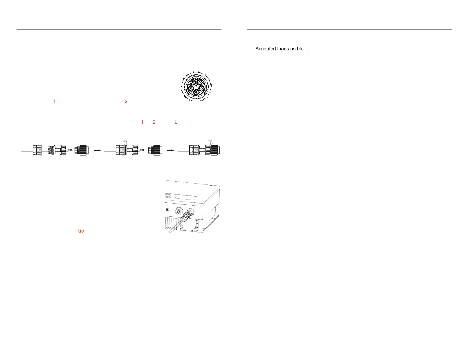
The similar way to assemble the EPS connector, pin , pin and pin are live lines, pin N
is neutral.
Fig.2.16
STEP2:
Connect the grid connector and the EPS connector
to the inverter. Just follow the markings on the
inverter to connect them correctly.
2.7
Power key and Declara
n for EPS Loads
Fig.2.17
The power button on the rear panel is only used for EPS function.
※When mains power does not exist and EPS function is enabled, press and hold for 3
seconds, the inverter will enter backup mode;
※When inverter operates in backup mode, press and hold for 3 seconds, inverter will exit
backup mode;
※ When inverter gi
ves an alarm and shutdown in backup mode, press and hold for 3
seconds, inverter will clear alarm.
※Inductive load: a non-frequency conversion air conditioner within 1.5P can be connected
to EPS side. Two or more may cause EPS output unstable.
Do not connect 3-phase inductive load(like motor) without Neutral line to EPS side.
※Capacitive load: Total power <=0.6*nominal power of model.
2.8 Smart meter connection
Please Refer to the connection instructions in the meter
box for connection
2.6 Grid & EPS Connection
Use the AC connectors from accessory box for grid and EPS connection. An external AC
breaker(32A) is needed for on-grid connection to isolate from grid
when necessary .
STEP1:
Note: Pi
Assemble the grid connector. Follow the markings on th
e
connectors, make sure 3L/N/PE lines are connected correctly.
n
connect to grid phase A, pin c onnect to
phase B and pinL to phase C. F
ig.2.15
w