EasyManua.ls Logo

THORENS TD125 - Operation

THORENS TD125
22 pages
Print Icon
To Next Page IconTo Next Page
To Previous Page IconTo Previous Page
Loading...
The
spring
mounted
parts
of
the
turntable
are
connect
ed
to
the
fixed
unit
plate
by
ground
lead
D.
Lug
E
should
be
fastened
on
the
metal
frame
by
the
corre-
sponding
set
screw
of
the
pick-up
wooden
board.
lf
necessary
for
particular
cartridges
or
amplifiers,
two
different
wiring
systems
may
be
easily
realized:
3
wire
system
Connect
lugs
3
and
4
on
the
terminal
strip
with
a
wire
B;
the
shields
of
both
channels
are
thus
connected
together
and
to
the
unit
plate
5
wire
system.
When
the
ground
for
the
turntable
cannot
be
returned
to
the
amplifier
ground
through
the
signal
carrying
shieldings,
the
wire
connecting
lugs
t
and
3
should
be
cut
at
A
and
a
separate
insulated
wire
C
connected
from
lug
1
to
the
common
grounding
point
for
the
amplifiers.
6.
OPERATION
6.1.
AC
Mains
power
supply
connection
The
turntable
TD
125
may
be
operated
at
any
AC
mains
power
supply.
For
voltages
between
210
and
240
V
the
small
fuse
5x20
mm,
100
mA,
slow-blow
has
to
be
attached
to
the
fitting
fuse
holders.
For
voltages
between
110
and
130
the
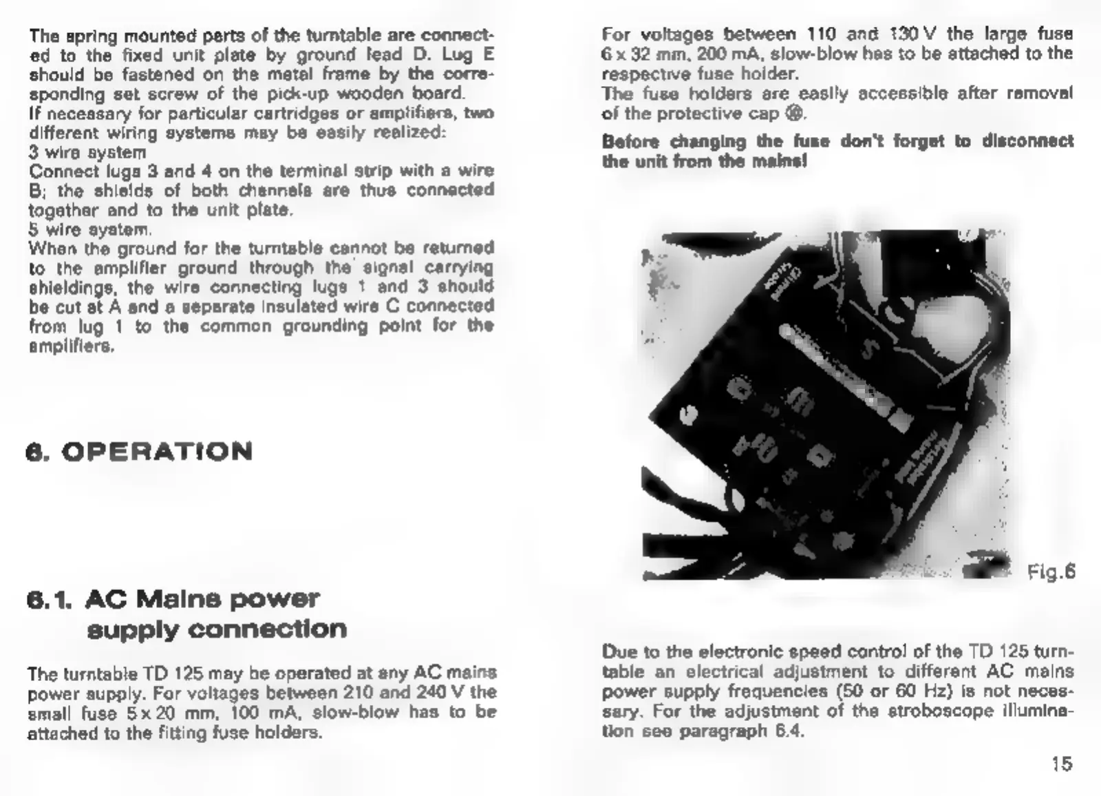
large fuse
6
x
32
mm,
200
mA,
slow-blow
has
to
be
attached
to
the
respective
fuse
holder,
The
fuse
holders
are
easily
accessible
after
removal
of
the
protective
cap
@.
Before
changing
the
fuse
don't
forget
to
disconnect
the
unit
from
the
mains!
(ai
Fig.
Due
to
the
electronic
speed
control
of
the
TD
125
turn-
table
an
electrical
adjustment
to
different
AC
mains
power
supply
frequencies
(50
or
60
Hz)
is
not
neces-
sary.
For
the
adjustment
of
the
stroboscope
illumina-
tion
see
paragraph
64.
15