Optical Chopper System
18488-D02 Rev G, September 24, 2012 Page 4 www.thorlabs.com
Table of Figures
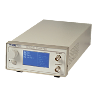
Figure 1: Front Panel ............................................................................................................................. 7
Figure 2: Rear Panel .............................................................................................................................. 7
Figure 3: Circuit Board Layout with 110/220 VAC Switch ................................................................ 21
Figure 4: Console Dimensional Drawing ............................................................................................ 26
Figure 5: Chopper Head Dimensional Drawing .................................................................................. 27