Optical Chopper System
18488-D02 Rev G, September 24, 2012 Page 7 www.thorlabs.com
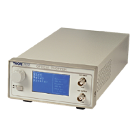
Front Panel Description
Figure 1: Front Panel
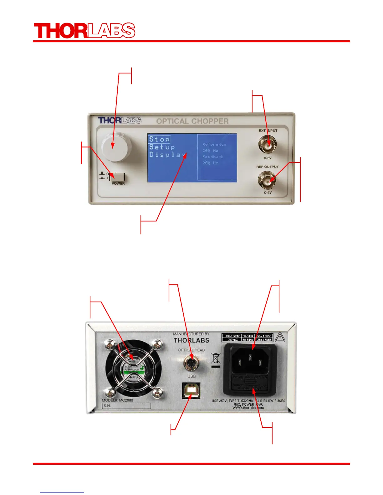
Rear Panel Description
Figure 2: Rear Panel
Control Knob
This knob is used to highlight and select menu items.
LCD Display
The controller menus are displaye
h
r
Power
Press to toggle
owe
Ext Input
The external reference signal is connected to this
input BNC (TTL / CMOS logic level).
Ref Output
The reference
output signal
selected by the
reference out menu
(CMOS logic
level
.
Cooling Fan
Do not block when the
unit is operating.
Modular Interface
Connector for the
optical hea
AC input receptacle
Requires an IEC compatible
plug with ground terminal.
Cord supplied for US
o
eration.
Fuse Holder
The system fuse is
installed here.
USB 2.0 Por